


User’s Manual
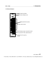
45
PART 2 DA264
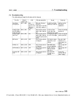
5. I/O Allocation and Programming
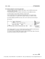
5.2 D/A conversion data
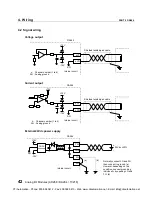
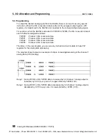
To output the desired analog signals from the DA264, simply write the appropriate data into the
assigned I/O registers YW(n) to YW(n+3) for the DA264.
The data of YW(n) to YW(n+3) are transferred to the DA264 at the T2’s batch I/O processing.
Then in the DA264, these D/A conversion data are converted into the analog signals and
output from the DA264.
The I/O register assignment is as follows.
YW(n) ........ D/A conversion data for channel 1
YW(n+1) .... D/A conversion data for channel 2
YW(n+2) .... D/A conversion data for channel 3
YW(n+3) .... D/A conversion data for channel 4
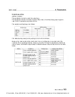
The conversion data to be written into the YW register is dependent on the output type as
follows.
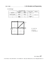
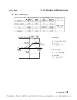
±±±±
10V range:
D/A conversion data
Hexadecimal
Integer
Output voltage
Resolution
Upper limit
H7F80
32640
+10.2 V
:
:
:
Full scale (positive)
H7D00
32000
+10 V
:
:
:
H0001
1
+0.3125 mV
0
H0000
0
0 V
HFFFF
-1
-0.3125 mV
:
:
:
Full scale (negative)
H8300
-32000
-10 V
:
:
:
Lower limit
H8080
-32640
-10.2 V
0.3125 mV / bit
A = 0.3125
×
D
D: Digital data
A: Analog signal (mV)
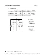
HC000
-16384
H8000
-32768
0
H3FFF
16383
H7FFF
32767
Analog output value
+10V
H7D00
32000
+5.1196V
-5.12V
-10V
H8300
-32000
Digital data
CTi Automation - Phone: 800.894.0412 - Fax: 208.368.0415 - Web: www.ctiautomation.net - Email: [email protected]