
116
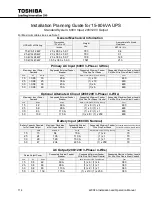
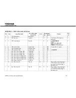
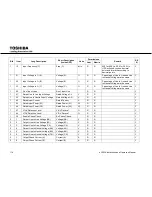
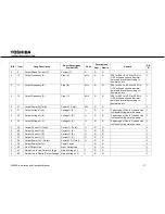
4200FA Installation and Operation Manual
Blk
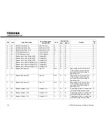
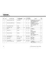
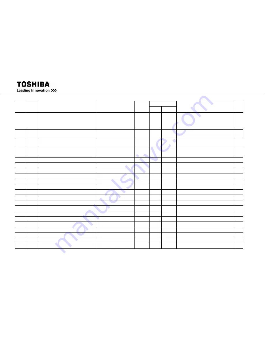
Item
Long Description
Short Description
(Inside UPS)
Units
Permissions
Remark
RE
III
User
Admin
1
12
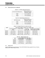
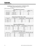
Input Frequency (C)
Freq (C)
dHz
R
R
600 for 60.0 Hz, 500 for 50.0 Hz.
UPS will send you one decimal
point and format it according to
decimal points
Y
1
21
Input Voltage in % (A)
Voltage (A)
%
R
R
Percentage of Line to Line and Line
to Neutral Voltage are the same
Y
1
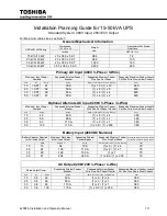
22
Input Voltage in % (B)
Voltage (B)
%
R
R
Percentage of Line to Line and Line
to Neutral Voltage are the same
Y
1
23
Input Voltage in % (C)
Voltage (C)
%
R
R
Percentage of Line to Line and Line
to Neutral Voltage are the same
Y
1
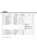
40
No of Input Lines
No of Input Line
R
R
Y
1
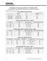
41
Rated Line to Line Input Voltage
Rated Voltage L-L
V
R
R
Y
1
42
Rated Line to Neutral Input Voltage
Rated Voltage L-N
V
R
R
Y
1
43
Rated Input Current
Rated Current
A
R
R
Y
1
45
Rated Input Power (W)
Rated Power (W)
W
R
R
Y
1
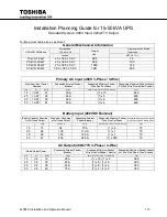
46
Rated Input Power (VA)
Rated Power (VA)
VA
R
R
Y
1
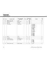
47
VIUV Detection Level
VIUV DeLevel
%
R
R
Y
1
49
VIOV Detection Level
VIOV DeLevel
%
R
R
Y
1
58
Enable Phase Check
En Phase Check
R
R
Y
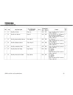
2
1
Output Line to Line Voltage (AB)
Voltage (AB)
V
R
R
Y
2
2
Output Line to Line Voltage (BC)
Voltage (BC)
V
R
R
Y
2
3
Output Line to Line Voltage (CA)
Voltage (CA)
V
R
R
Y
2
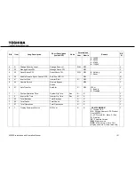
4
Output Line to Neutral Voltage (AN) Voltage (AN)
V
R
R
Y
2
5
Output Line to Neutral Voltage (BN) Voltage (BN)
V
R
R
Y
2
6
Output Line to Neutral Voltage (CN) Voltage (CN)
V
R
R
Y
2
7
Output Phase Current (A)
Current (A)
A
R
R
Y
2
8
Output Phase Current (B)
Current (B)
A
R
R
Y
Содержание 4200FA Series
Страница 2: ...4200FA Installation and Operation Manual ...
Страница 12: ...vi 4200FA Installation and Operation Manual ...
Страница 16: ...4 4200FA Installation and Operation Manual NOTE This Label for Battery Units Only ...
Страница 110: ...98 4200FA Installation and Operation Manual 36 3 in 922 mm ...
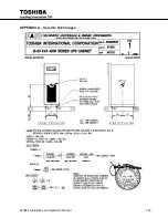
Страница 115: ...4200FA Installation and Operation Manual 103 APPENDIX A Seismic Anchorages ...
Страница 116: ...104 4200FA Installation and Operation Manual ...
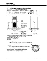
Страница 117: ...4200FA Installation and Operation Manual 105 ...
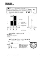
Страница 118: ...106 4200FA Installation and Operation Manual ...
Страница 136: ...124 4200FA Installation and Operation Manual ...
Страница 137: ......


