Nov. 1997 © TOSHIBA
17 - 9
3560/70 INSTALLATION
5. The automatic adjustment of the auto-
toner sensor is complete and “Install
new cartridge” is shown on the
message display.
.
If the adjustment has finished abnor-
mally, the machine stops its operation
and displays the CALL SERVICE.
Then, for the subsequent adjustment
of the auto-toner sensor, follow the
procedure described in the Service
Manual.
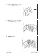
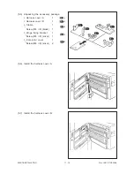
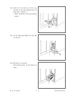
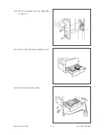
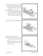
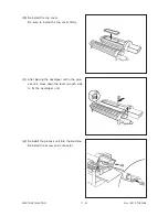
(26) Shake the new toner cartridge to the right
and to the left 5 or 6 times to loosen the
toner inside.
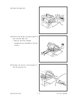
(25) <Procedure for installing the toner car-
tridge>
Open the front cover.
Содержание 3560
Страница 20: ...Nov 1997 TOSHIBA 2 13 3560 70 GENERAL 2 3 Wire Harness Location Diagram A Location diagram for upper unit ...
Страница 21: ...3560 70 GENERAL 2 14 Nov 1997 TOSHIBA B Location diagram for lower unit ...
Страница 72: ...Nov 1997 TOSHIBA 13 25 3560 70 CIRCUIT DIAGRAMS 13 3 Power Supply Circuit PS ACC A 115 V ...
Страница 73: ...3560 70 CIRCUIT DIAGRAMS 13 26 Nov 1997 TOSHIBA B 230 V ...
Страница 77: ...Nov 1997 TOSHIBA 15 1 3560 70 PC BOARD 15 PC BOARD ASSEMBLY 15 1 PWA LGC ...
Страница 78: ...3560 70 PC BOARD 15 2 Nov 1997 TOSHIBA 15 2 PWA PNL ...
Страница 79: ...Nov 1997 TOSHIBA 15 3 3560 70 PC BOARD 15 3 PWA KEY KEY1 KEY2 ...
Страница 80: ...3560 70 PC BOARD 15 4 Nov 1997 TOSHIBA 15 4 PWA ERS ...
Страница 81: ...Nov 1997 TOSHIBA 15 5 3560 70 PC BOARD 15 5 PS ACC A 1 115V ...
Страница 82: ...3560 70 PC BOARD 15 6 Nov 1997 TOSHIBA A 2 230V ...


