3560/70 INSTALLATION
17 - 14
Nov. 1997 © TOSHIBA
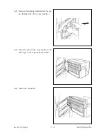
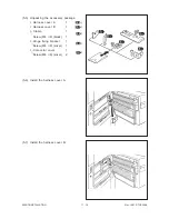
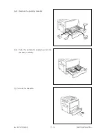
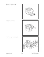
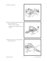
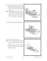
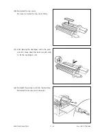
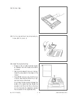
(3) Pulling out the handles located on both
sides of the body.
Keep the machine horizontal and the
handles firmly grasped when transporting.
(4) After setting the machine on the appropriate
stand, pushing the handles into the body.
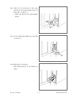
Fix the handles by using the screws and the
brackets included in the package.
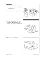
(5-1) Remove the packing material inside of the
large-capacity feeder.
Содержание 3560
Страница 20: ...Nov 1997 TOSHIBA 2 13 3560 70 GENERAL 2 3 Wire Harness Location Diagram A Location diagram for upper unit ...
Страница 21: ...3560 70 GENERAL 2 14 Nov 1997 TOSHIBA B Location diagram for lower unit ...
Страница 72: ...Nov 1997 TOSHIBA 13 25 3560 70 CIRCUIT DIAGRAMS 13 3 Power Supply Circuit PS ACC A 115 V ...
Страница 73: ...3560 70 CIRCUIT DIAGRAMS 13 26 Nov 1997 TOSHIBA B 230 V ...
Страница 77: ...Nov 1997 TOSHIBA 15 1 3560 70 PC BOARD 15 PC BOARD ASSEMBLY 15 1 PWA LGC ...
Страница 78: ...3560 70 PC BOARD 15 2 Nov 1997 TOSHIBA 15 2 PWA PNL ...
Страница 79: ...Nov 1997 TOSHIBA 15 3 3560 70 PC BOARD 15 3 PWA KEY KEY1 KEY2 ...
Страница 80: ...3560 70 PC BOARD 15 4 Nov 1997 TOSHIBA 15 4 PWA ERS ...
Страница 81: ...Nov 1997 TOSHIBA 15 5 3560 70 PC BOARD 15 5 PS ACC A 1 115V ...
Страница 82: ...3560 70 PC BOARD 15 6 Nov 1997 TOSHIBA A 2 230V ...


