1-5
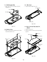
3. Remove the connectors (4) from the five locations,
then remove the main PC board (5).
Fig. 1-1-17
Note:
• Return the wiring to their original positions during
assembly.
1-11. Front Net, Speaker
1. Remove four screws (1).
2. Remove the GND lead wire (2), then remove the front
net assembly (3).
3. Remove four screws (4), then remove the right speaker
(5), four screws (6) and the left speaker (7).
4. The front net assembly (3) will come apart to the front
net (8) and the chassis (9) when claws A are released.
Fig. 1-1-18
1-12.Switch PC Board
1. Remove the cushion (1).
2. Remove the connector (2).
3. Remove one screw (3), then remove the switch PC
board (4).
4. Remove the power button (5), the power button cover
(6) and the 5-knob switch button (7).
Fig. 1-1-19
1-13.Hinge, Top Cover
1. Remove two screws (1), remove the left support (2)
and the left hinge (3).
2. Remove two screws (4), the right support (5) and the
right hinge (6), then remove the top cover (7).
Fig. 1-1-20
Connector (4)
Connector (4)
Main PC board (5)
Bundled wires
Screws (1)
GND lead wire (2)
Front net assembly (3)
Screws (4)
Screws (6)
Right speaker (5)
Left speaker (7)
Front net (8)
Chassis (9)
Claw A
Claw A
Claw A
Claw A
Claw A
Cushion (1)
Connector (2)
Screw (3)
Switch PC board (4)
Power button cover (5)
Power button (6)
5-knob switch
button (7)
Screws (1)
Left support (2)
Left hinge (3)
Screws (4)
Right
support (5)
Right hinge (6)
Top cover (7)
GND lead wire
GND
lead wire
Содержание 15DL72
Страница 1: ...LCD TV SERVICE MANUAL FILE NO 050 200224 15DL72 DOCUMENT CREATED IN JAPAN Oct 2002 ...
Страница 6: ...This page is not printed ...
Страница 46: ...10 1 3 4 A B C D E G 2 5 6 7 8 9 F Fig 2 4 2 U001 Main PC board Bottom side 2 44 2 43 ...
Страница 48: ...2 46 This page is not printed ...
Страница 56: ...3 8 This page is not printed ...
Страница 57: ...TOSHIBA CORPORATION 1 1 SHIBAURA 1 CHOME MINATO KU TOKYO 105 8001 JAPAN ...

