1 - 34
1550 ADJUSTMENT
Oct. 1995 © TOSHIBA CORP.
1.11 Checking and Adjustment of Developer Bias Output
<Adjustment procedure>
(Use code 40 in test mode 05.)
1.
Remove the process unit.
2.
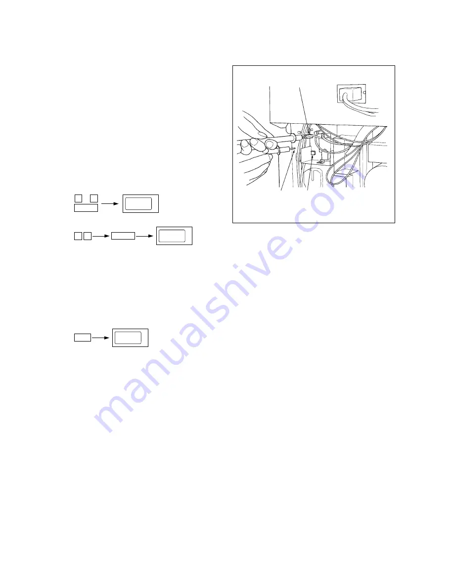
How to connect digital tester to the machine
• Connect (+) terminal of digital tester to bias
connector (OUT 5)
• Connect (–) common terminal of digital
tester to machine frame.
• Set digital tester to 1000 VDC range.
3.
4.
5.
Check voltage value using digital tester.
–DC200 V ±5 V
OUT 5
Frame earth
VR81
0
5
Power
AJ
4 0
128
C/S
(Output stop)
AJ
6.
If adjustment is required, perform adjustment through VR81 (Bias). (Do not touch the zoom keys
and the digital keys.)
7.
Note: If an overall misty effect is observed, even though exposure is sufficient, increase bias output
through VR81 (Bias). However, when bias output is over-increased, the image contrast declines,
causing a generation of bias leakage, and the carrier tends to stick to the drum easily.


