background image

13

Outdoor Unit

Installation Manual

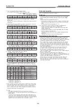
3. Turn on the circuit breaker to supply electricity.
  In the initial LED display status, D805 is lighted as below.

™

 : ON, 

˜

 : OFF,   : Rapid Flashing (5 times/sec.),

¯

 : Slow Flashing (1 time/sec.)

D800

D801

D802

D803

D804

D805

˜

˜

˜

˜

˜

™

Start running all the indoor units connected to the outdoor unit in the 
cooling mode.
(The indoor unit in the room that doesn’t operate the cooling mode cannot 
be checked.)

4. After 5 minutes, hold down SW01 for at least 5 seconds, and check that 

D800 is lighted and D804 light is 

fl

 ashing (1 time/sec.).

D800

D801

D802

D803

D804

D805

™

˜

˜

˜

¯

˜

5. Press the SW01 4 times until the LED is displayed as below.

D800

D801

D802

D803

D804

D805

˜

˜

™

˜

˜

6. Press SW02 for 1 times. Then D805 light is 

fl

 ashing (5 times/sec.).

D800

D801

D802

D803

D804

D805

˜

˜

™

˜

7. Hold down SW02 for at least 5 seconds. Then the wiring/piping check 

starts automatically. (The LED display is lighted for a moment.)

D800

D801

D802

D803

D804

D805

˜

˜

™

˜

¯

™

•  If no problems are detected, the checking operation returns to the 

normal operation automatically. The LED is displayed as below.

D800

D801

D802

D803

D804

D805

˜

˜

˜

˜

˜

™

8. The below is displayed when the error is detected.
  (* Repetition of 3 sec ON / 0.5 sec OFF)

D800

D801

D802

D803

D804

D805

™

*

™

*

™

*

™

*

™

*

™

  Press the SW01 3 times until the LED is displayed as below, to check the 

room judged as error.

D800

D801

D802

D803

D804

D805

˜

™

˜

˜

˜

  Incorrect wiring/piping can be checked by pressing SW02. The LED is 

displayed as below. Turn off the circuit breaker, then check wiring/piping 
again.

Check result

D800 D801 D802 D803 D804 D805

Description

˜

˜

˜

˜

˜

¯

Normal operation (no error)

™

˜

˜

˜

˜

¯

Trouble in unit A

˜

™

˜

˜

˜

¯

Trouble in unit B

˜

˜

™

˜

˜

¯

Trouble in unit C

™

™

˜

˜

˜

¯

Trouble in unit A and B

™

˜

™

˜

˜

¯

Trouble in unit A and C

˜

™

™

˜

˜

¯

Trouble in unit B and C

™

™

™

˜

˜

¯

Trouble in unit A, B and C

•  The D800 LED represents unit A.
•  The D801 LED represents unit B.
•  The D802 LED represents unit C.

9. When you want to start over the operation of the SW01 and SW02, press 

the SW01 and the SW02 at the same time for 5 sec. (The procedure will 
set back to step 3.) However, do not execute the operation during the 
check. If by any chance the check is stopped by the operation, start over 
the check after turning off the power once.

10. Notes

•  It sometimes takes about 30 minutes maximum for the check.
•  During the check, the compressor and the fan of the outdoor/indoor unit 

repeat ON/OFF.

•  You cannot check wiring/piping when the external temperature is 5°C 

or less. Also, there is a possibility to misjudge if the indoor temperature 
becomes too low by cooling operation. In that case, execute the cooling 
operation for per room and check if the connection is normal.

„

Gas Leak Inspection

Refer to the “

„

 Gas Leak Inspection” on page 11.

„

Test run

1. If you perform the test run in summer, start running in the cooling mode 

fi

 rst to decrease the temperature of the room, then run in the heating 

mode.

  (Heating mode: Set the temperature to 30°C.)

•  If you perform the test run in winter, start running in the heating mode 

fi

 rst to increase the temperature of the room, then run in the cooling 

mode.

  (Cooling mode: Set the temperature to 17°C.)

2. For the test run, be sure to satisfy the following conditions below:

-  Perform the test run for each indoor unit respectively.
-  Perform the test run for about 10 minutes in both the cooling mode 

and the heating mode.

•  You can perform the test run in the cooling/heating mode by utilizing 

the thermo sensor of the indoor unit.

  Cooling mode: Warm the thermo sensor using an appliance such as 

a hair dryer.

  Heating mode: Put a cold towel on the thermo sensor.

„

Instructions for the Customers

•  Explain to the customers the proper operation procedure and let them 

operate the air conditioner along with the supplied instruction manual.

•  When multiple indoor units are connected to the outdoor unit, the cooling 

mode and the heating mode are not available at the same time.

  When multiple indoor units are running at the same time, the operation 

mode of the unit which starts running 

fi

 rst is applied to the other units.

•  When you start running the indoor unit or change the operation mode, the 

unit starts running after 3 minutes. This is due to the protection function of 
the unit, not a malfunction.

•  When the external temperature becomes low, the pre-heating of the 

compressor starts to protect it. Keep the circuit breaker on for use.

  The electricity consumption during pre-heating is about 30 W.
  If the circuit breaker is turned off, the indoor unit may not start running for 

about 10 minutes or more.

•  Electronic expansion valves are used for the outdoor unit.
  When you turn on the power, the outdoor unit starts clattering every 1 or 

2 months. This clattering is not a malfunction, but occurs when the unit is 
returning to the default setting for optimised control.

•  While an indoor unit is running in the heating mode, the outdoor unit 

supplies refrigerant to the other indoor units which are not running.

  Therefore, noise may come from the other indoor units or the exterior of 

them may become warm.

Содержание 13340

Страница 1: ...oor Unit AIR CONDITIONER MULTI SPLIT TYPE Model name RAS 2M10U2AVG E RAS 2M14U2AVG E RAS 2M18U2AVG E RAS 3M18U2AVG E NOTE Descriptions about operations for the 3 indoor units in this manual are not applicable to RAS 2M10U2AVG E RAS 2M14U2AVG E and RAS 2M18U2AVG E R32 ...

Страница 2: ...9 Test run 12 10 Pump down Operation 14 11 Troubleshooting 14 12 Appendix 15 Please read this Installation Manual carefully before installing the Air Conditioner This Manual describes the installation method of the outdoor unit For installation of the indoor unit refer to the Installation Manual attached to the indoor unit IMPORTANT NOTICE For details on how to install the indoor units refer to th...

Страница 3: ...cates that incorrect use of this unit can result in a high possibility of severe injury 1 or death WARNING It indicates that incorrect use of this unit may cause severe injury or death CAUTION It indicates that incorrect use of this unit may cause personal injury 2 or property damage 3 1 A severe injury refers to blindness injury burns hot or cold electrical shock bone fracture or poisoning that l...

Страница 4: ... WELL AS THE ADOPTION OF THIS NEW REFRIGERANT REFRIGERATING MACHINE OIL HAS ALSO BEEN CHANGED THEREFORE DURING INSTALLATION WORK BE SURE THAT WATER DUST FORMER REFRIGERANT OR REFRIGERATING MACHINE OIL DOES NOT ENTER THE REFRIGERATION CYCLE OF A NEW REFRIGERANT AIR CONDITIONER TO AVOID MIXING REFRIGERANT AND REFRIGERATING MACHINE OIL THE SIZES OF CHARGING PORT CONNECTING SECTIONS ON THE MAIN UNIT A...

Страница 5: ...TING THE INDOOR UNIT AND CAUSING A FIRE HAZARD PLACE THE UNIT WELL AWAY MORE THAN 2 M FROM HEAT SOURCES SUCH AS RADIATORS HEATERS FURNACE STOVES ETC WHEN MOVING THE AIR CONDITIONER FOR INSTALLING IT IN ANOTHER PLACE AGAIN BE VERY CAREFUL NOT TO GET THE SPECIFIED REFRIGERANT R32 WITH ANY OTHER GASEOUS BODY INTO THE REFRIGERATION CYCLE IF AIR OR ANY OTHER GAS IS MIXED IN THE REFRIGERANT THE GAS PRES...

Страница 6: ...d the manual A dedicated circuit and the rated voltage must be used Insufficient power supply or improper installation may cause electrical shock or fire Use a cabtyre cable to connect wires in the indoor outdoor units Midway connection stranded wire and single wire connections are not allowed Improper connection or fixing may cause a fire Wiring between the indoor unit and outdoor units must be w...

Страница 7: ...st or injury Do not modify the power cable connect the cable midway or use a multiple outlet extension cable Doing so may cause contact failure insulation failure or excess current resulting in fire or electrical shock If you detect any damage do not install the unit Contact your supplying dealer immediately Never modify this unit by removing any of the safety guards or bypassing any of the safety...

Страница 8: ... for installation work Failure to do so may cause personal injury when handling parts with sharp edges Do not touch the air intake section or the aluminium fins of the outdoor unit It may cause injury Do not install the outdoor unit in a place which can be a nest for small animals Small animals could enter and contact internal electrical parts causing a failure or fire Request the user to keep the...

Страница 9: ...s other than the above the safety protection functions may be activated Example of indoor unit class RAS B10UFV E1 is abbreviated as 10 Indoor unit class Standard connecting pipe diameter RAS 2M10U2AVG E RAS 2M14U2AVG E RAS 2M18U2AVG E RAS 3M18U2AVG E Unit C 07 or 10 or 13 6 35 9 52 mm Unit B 07 or 10 or 13 or 16 6 35 9 52 mm 6 35 9 52 mm 6 35 9 52 mm 3 6 35 9 52 mm 3 Unit A 07 or 10 or 13 or 16 6...

Страница 10: ...if outdoor work is difficult you can change the procedure For example by making adjustments to the wiring and piping lengths on the inside rather than the outside When using an air conditioner under low outside temperature conditions Outside temp 5 C or lower In COOL mode prepare a duct or wind shield so that it is not affected by the wind Necessary Space for Installation If you need to install th...

Страница 11: ... Do not remove the flare nuts for any ports you are not going to use for connection Do not leave the flare nut unattached for a long period of time Use a different diameter joint if the diameters of the connection port and connection piping are different Mount the different diameter joint on the connection port of the outdoor unit CAUTION KEEP IMPORTANT 6 POINTS FOR PIPING WORK 1 Take away dust an...

Страница 12: ...ffect the terminals If wiring connections are incomplete or cables are not fixed securely it may cause a fire Be sure to ground the outdoor unit Incomplete grounding may lead to an electric shock 3 Close the Handle Low of the gauge manifold valve fully then stop operating the vacuum pump Leave the gauge and pump as they are for 1 or 2 minutes then make sure that the compound pressure gauge reading...

Страница 13: ...for the power source and each indoor unit Connect the connecting cable to the terminal as identified by the matching numbers on the terminal block of the indoor and the outdoor unit 5 Fix the wiring connections for the power source and each indoor unit securely using a cord clamp 6 Attach the terminal cover and the valve cover Stripping Length of connecting cable for outdoor unit 55 5 5 30 1 2 3 5...

Страница 14: ... or less Also there is a possibility to misjudge if the indoor temperature becomes too low by cooling operation In that case execute the cooling operation for per room and check if the connection is normal Gas Leak Inspection Refer to the Gas Leak Inspection on page 11 Test run 1 If you perform the test run in summer start running in the cooling mode first to decrease the temperature of the room t...

Страница 15: ...he service valve at the liquid end 9 Make sure that the compound pressure gauge reading is 101 kPa 76 cmHg 10 Close the valve stem of the service valve at the gas end 11 The refrigerants collection operation is finished in maximum 10 minutes After the collection is finished promptly stop the operation of all the indoor unit There are cases that the compressor restarts 12 When you want to start ove...

Страница 16: ...ture of foreign matter is observed trouble will occur 8 When temporary installation and removal of the air conditioner are repeated such as when leased etc 9 If the type of refrigerator oil of the existing air conditioner is other than the following oil Mineral oil Suniso Freol S MS Synthetic oil alkyl benzene HAB Barrel freeze ester series PVE only of ether series The winding insulation of the co...

Страница 17: ......

Страница 18: ...144 9 Moo 5 Bangkadi Industrial Park Tivanon Road Tambol Bangkadi Amphur Muang Pathumthani 12000 Thailand 1116691098 ...

Отзывы: