background image

9

Outdoor Unit

Installation Manual

5

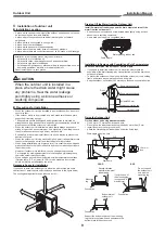
Installation of outdoor unit

„

Installation Location

•  A place which can bear the weight of the outdoor unit and does not cause 

an increase in noise level and vibration.

•  A place where the operation noise and air discharge do not disturb 

neighbours.

•  A place which is not exposed to strong wind.
•  A place free of combustible gas.
•  A place which does not block a passageway.
•  A place where the drain water does not cause any problems.
•  A place where there are no obstructions near its air intake or air discharge.

Installation in the following places may result in trouble:
•  A place with a lot of machine oil.
•  A place with saline-rich atmosphere such as a coastal area.
•  A place with high level of sul

fi

 de gas.

•  A place where high-frequency waves are likely to be generated, such as 

from audio equipment, welders, or medical equipment.

Do not install the unit in such places.

CAUTION

When the outdoor unit is installed in a 
place where the drain water might cause 
any problems, Seal the water leakage 
point tighty using a silicone adhesive or 
caulking compound.

„

Precautions for Installation

•  When the outdoor unit is to be installed in an elevated position, be sure to 

secure its feet.

•  If the outdoor unit is to be mounted on a wall, make sure the base plate 

supporting it is sturdy enough.

•  The base plate should be designed and manufactured to maintain its 

strength over a long period of time, and suf

fi

 cient consideration should be 

given to ensure that the outdoor unit will not fall.

•  When the outdoor unit is installed in a place that is always exposed to 

strong wind such as a coastal area or on a high story of a building, secure 
the normal fan operation using a duct or a wind shield.

•  Especially in windy areas, install the unit in such a way as to prevent the 

admission of wind.

•  When the outdoor unit is to be mounted high on a wall, take particular care 

to ensure that parts do not fall, and that the installer is protected.

•  When doing installation work at ground level, it is usual to make wiring and 

pipe connections to the indoor units 

fi

 rst, and then to make connections to 

the outdoor units.

  However, if outdoor work is dif

fi

 cult, you can change the procedure.

  For example, by making adjustments to the wiring and piping lengths on 

the inside (rather than the outside).

•  When using an air conditioner under low outside temperature conditions 

(Outside temp: -5 °C or lower) In COOL mode, prepare a duct or wind 
shield so that it is not affected by the wind.

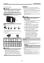
Necessary Space for Installation

If you need to install the outdoor unit in a location where there are some 
obstructions or a wall, secure suf

fi

 cient space as shown in the 

fi

 gure below.

The cooling/heating effect may be reduced by 10%.

600 mm or more

100 mm or more

600 mm or more

600 mm or more

100 mm or more

Draining Off the Water from the Outdoor Unit

Install 2 waterproof rubber caps and the drain nipple to drain off the 
water from the outdoor unit.

•  Seal the knock-out holes and screw/thread areas tightly using a silicon 

adhesive or a caulking compound.

•  Use a drain pan to apply a centralized drain.

Drain nipple

Water-proo

fi

 ng rubber cap

Installation in Regions with Snowfall and Cold Temperatures

Do not use waterproof rubber caps or a drain nipple.

•  If you need to install the outdoor unit in a location where there is a 

possibility of the drain freezing, pay close attention so that the drain does 
not become frozen.

•  To protect the outdoor unit from snow, install the outdoor unit on a holding 

frame, and attach a snow protection hood and plate.

•  Keep the outdoor unit at least 500 mm above the snow accumulation line.

Snow protection plate

Snow protection hood

At least 500 mm

Snow accumulation line

Holding frame

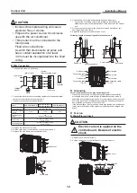
Anchor bolts

Front

Fixing the Outdoor Unit

Fix the outdoor unit using attachment bolts.

•  Use 8 mm or 10 mm anchor bolts and nuts.
•  Do not allow the attachment bolts to protrude by more than 15 mm.
•  Install the outdoor unit at ground level.
•  Attach the vibration-proof rubber pads under the 

fi

 xing legs.

Drain nipple mounting hole

508

600

99

100

Drain hole

15 mm or 
less

GOOD

BAD

Absorb vibration 
with vibration-proof 
rubber pads

If only the end of 
the mounting leg 
is supported, it 
may deform.

Do not support 
the outdoor unit 
only with the 
mounting leg.

Mounting 
leg

Foundation

Bottom plate of 
outdoor unit

Foundation

Support the bottom surface of the mounting 
leg that is in contact with and underneath the 
bottom plate of the outdoor unit.

Foundation

351

330

54

Содержание 13340

Страница 1: ...oor Unit AIR CONDITIONER MULTI SPLIT TYPE Model name RAS 2M10U2AVG E RAS 2M14U2AVG E RAS 2M18U2AVG E RAS 3M18U2AVG E NOTE Descriptions about operations for the 3 indoor units in this manual are not applicable to RAS 2M10U2AVG E RAS 2M14U2AVG E and RAS 2M18U2AVG E R32 ...

Страница 2: ...9 Test run 12 10 Pump down Operation 14 11 Troubleshooting 14 12 Appendix 15 Please read this Installation Manual carefully before installing the Air Conditioner This Manual describes the installation method of the outdoor unit For installation of the indoor unit refer to the Installation Manual attached to the indoor unit IMPORTANT NOTICE For details on how to install the indoor units refer to th...

Страница 3: ...cates that incorrect use of this unit can result in a high possibility of severe injury 1 or death WARNING It indicates that incorrect use of this unit may cause severe injury or death CAUTION It indicates that incorrect use of this unit may cause personal injury 2 or property damage 3 1 A severe injury refers to blindness injury burns hot or cold electrical shock bone fracture or poisoning that l...

Страница 4: ... WELL AS THE ADOPTION OF THIS NEW REFRIGERANT REFRIGERATING MACHINE OIL HAS ALSO BEEN CHANGED THEREFORE DURING INSTALLATION WORK BE SURE THAT WATER DUST FORMER REFRIGERANT OR REFRIGERATING MACHINE OIL DOES NOT ENTER THE REFRIGERATION CYCLE OF A NEW REFRIGERANT AIR CONDITIONER TO AVOID MIXING REFRIGERANT AND REFRIGERATING MACHINE OIL THE SIZES OF CHARGING PORT CONNECTING SECTIONS ON THE MAIN UNIT A...

Страница 5: ...TING THE INDOOR UNIT AND CAUSING A FIRE HAZARD PLACE THE UNIT WELL AWAY MORE THAN 2 M FROM HEAT SOURCES SUCH AS RADIATORS HEATERS FURNACE STOVES ETC WHEN MOVING THE AIR CONDITIONER FOR INSTALLING IT IN ANOTHER PLACE AGAIN BE VERY CAREFUL NOT TO GET THE SPECIFIED REFRIGERANT R32 WITH ANY OTHER GASEOUS BODY INTO THE REFRIGERATION CYCLE IF AIR OR ANY OTHER GAS IS MIXED IN THE REFRIGERANT THE GAS PRES...

Страница 6: ...d the manual A dedicated circuit and the rated voltage must be used Insufficient power supply or improper installation may cause electrical shock or fire Use a cabtyre cable to connect wires in the indoor outdoor units Midway connection stranded wire and single wire connections are not allowed Improper connection or fixing may cause a fire Wiring between the indoor unit and outdoor units must be w...

Страница 7: ...st or injury Do not modify the power cable connect the cable midway or use a multiple outlet extension cable Doing so may cause contact failure insulation failure or excess current resulting in fire or electrical shock If you detect any damage do not install the unit Contact your supplying dealer immediately Never modify this unit by removing any of the safety guards or bypassing any of the safety...

Страница 8: ... for installation work Failure to do so may cause personal injury when handling parts with sharp edges Do not touch the air intake section or the aluminium fins of the outdoor unit It may cause injury Do not install the outdoor unit in a place which can be a nest for small animals Small animals could enter and contact internal electrical parts causing a failure or fire Request the user to keep the...

Страница 9: ...s other than the above the safety protection functions may be activated Example of indoor unit class RAS B10UFV E1 is abbreviated as 10 Indoor unit class Standard connecting pipe diameter RAS 2M10U2AVG E RAS 2M14U2AVG E RAS 2M18U2AVG E RAS 3M18U2AVG E Unit C 07 or 10 or 13 6 35 9 52 mm Unit B 07 or 10 or 13 or 16 6 35 9 52 mm 6 35 9 52 mm 6 35 9 52 mm 3 6 35 9 52 mm 3 Unit A 07 or 10 or 13 or 16 6...

Страница 10: ...if outdoor work is difficult you can change the procedure For example by making adjustments to the wiring and piping lengths on the inside rather than the outside When using an air conditioner under low outside temperature conditions Outside temp 5 C or lower In COOL mode prepare a duct or wind shield so that it is not affected by the wind Necessary Space for Installation If you need to install th...

Страница 11: ... Do not remove the flare nuts for any ports you are not going to use for connection Do not leave the flare nut unattached for a long period of time Use a different diameter joint if the diameters of the connection port and connection piping are different Mount the different diameter joint on the connection port of the outdoor unit CAUTION KEEP IMPORTANT 6 POINTS FOR PIPING WORK 1 Take away dust an...

Страница 12: ...ffect the terminals If wiring connections are incomplete or cables are not fixed securely it may cause a fire Be sure to ground the outdoor unit Incomplete grounding may lead to an electric shock 3 Close the Handle Low of the gauge manifold valve fully then stop operating the vacuum pump Leave the gauge and pump as they are for 1 or 2 minutes then make sure that the compound pressure gauge reading...

Страница 13: ...for the power source and each indoor unit Connect the connecting cable to the terminal as identified by the matching numbers on the terminal block of the indoor and the outdoor unit 5 Fix the wiring connections for the power source and each indoor unit securely using a cord clamp 6 Attach the terminal cover and the valve cover Stripping Length of connecting cable for outdoor unit 55 5 5 30 1 2 3 5...

Страница 14: ... or less Also there is a possibility to misjudge if the indoor temperature becomes too low by cooling operation In that case execute the cooling operation for per room and check if the connection is normal Gas Leak Inspection Refer to the Gas Leak Inspection on page 11 Test run 1 If you perform the test run in summer start running in the cooling mode first to decrease the temperature of the room t...

Страница 15: ...he service valve at the liquid end 9 Make sure that the compound pressure gauge reading is 101 kPa 76 cmHg 10 Close the valve stem of the service valve at the gas end 11 The refrigerants collection operation is finished in maximum 10 minutes After the collection is finished promptly stop the operation of all the indoor unit There are cases that the compressor restarts 12 When you want to start ove...

Страница 16: ...ture of foreign matter is observed trouble will occur 8 When temporary installation and removal of the air conditioner are repeated such as when leased etc 9 If the type of refrigerator oil of the existing air conditioner is other than the following oil Mineral oil Suniso Freol S MS Synthetic oil alkyl benzene HAB Barrel freeze ester series PVE only of ether series The winding insulation of the co...

Страница 17: ......

Страница 18: ...144 9 Moo 5 Bangkadi Industrial Park Tivanon Road Tambol Bangkadi Amphur Muang Pathumthani 12000 Thailand 1116691098 ...

Отзывы: