47
Servicing the Fuses
Service Interval/Specification
The electrical system is protected by fuses. It requires no
maintenance; however, if a fuse blows, check the
component/circuit for a malfunction or short.
Fuse: Main F1—30 amp, blade-type
Charge Circuit F2—25 amp, blade-type
Optional Headlight Kit—10 amp, blade type
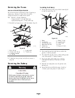
1. Raise the seat to gain access to the fuse holder (Fig. 60).
m–7724
1
2
3
4
5
Figure 60
1.
Main—30 amp
2.
Charge circuit—25 amp
3.
For optional Headlight
Kit—10 amp
4.
Ignition switch
5.
Throttle lever
2. To replace a fuse, pull out on the fuse to remove it
(Fig. 60).
Servicing the Battery
CALIFORNIA
Proposition 65 Warning
Battery posts, terminals, and related accessories
contain lead and lead compounds, chemicals
known to the State of California to cause cancer
and reproductive harm. Wash hands after
handling.
Warning
Installing the Battery
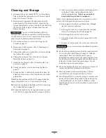
1. Position the battery in the tray with the terminal posts
toward the engine (Fig. 61).
1
9
5
2
6
7
10
4
3
8
11
7
m–5598
Figure 61
1.
Battery
2.
Terminal boot
3.
Positive battery cable
4.
Negative battery cable
5.
Ground wire
6.
Bolt, 1/4 x 3/4 inch
7.
Washer, 1/4 inch
8.
Locknut, 1/4 inch
9.
Battery clamp
10. J-bolts
11. Wing nut, 1/4 inch
2. First, install the positive (red) battery cable to the
positive (+) battery terminal.
3. Then install the negative battery cable and the ground
wire to the negative (–) battery terminal.
4. Secure the cables with 2 bolts (1/4 x 3/4 inch),
2 washers (1/4 inch), and 2 locknuts (1/4 inch)
(Fig. 61).
5. Slide the red terminal boot onto the positive (red)
battery post.
6. Secure the battery with J-bolts, clamp, 2 washers
(1/4 inch), and 2 wing nuts (1/4 inch) (Fig. 61).


