background image

Evaporative Emission Control Warranty Statement

California Evaporative Emission Control Warranty Statement

Your Warranty Rights and Obligations

Introduction

The California Air Resources Board and The Toro® Company are pleased to explain the evaporative emission control system’s warranty on your 2007 model

year equipment. In California, new equipment that use small off-road engines must be designed, built, and equipped to meet the State’s stringent anti-smog

standards. The Toro® Company must warrant the evaporative emission control system on your equipment for two years provided there has been no abuse,

neglect or improper maintenance of your equipment.
Your evaporative emission control system may include parts such as: fuel lines, fuel line ttings, and clamps.

Manufacturer’s Warranty Coverage:

This evaporative emission control system is warranted for two years. If any evaporative emission-related part on your equipment is defective, the part will be

repaired or replaced by The Toro® Company.

Owner’s Warranty Responsibilities:

As the equipment owner, you are responsible for performance of the required maintenance listed in your Operator’s Manual. The Toro® Company recommends

that you retain all receipts covering maintenance on your equipment, but The Toro® Company cannot deny warranty solely for the lack of receipts.

As the equipment owner, you should however be aware that The Toro® Company may deny you warranty coverage if your emission warranty parts have failed

due to abuse, neglect, or improper maintenance or unapproved modications.

You are responsible for presenting your equipment to an Authorized Service Dealer as soon as the problem exists. The warranty repairs should be completed

in a reasonable amount of time, not to exceed 30 days. If you have a question regarding your warranty coverage, you should contact The Toro® Company at

1-952–948–4027 or call us toll free at the number listed in your Toro Warranty statement.

Defects Warranty Requirements:

1.

The warranty period begins on the date the engine or equipment is delivered to an ultimate purchaser.

2.

General Evaporative Emissions Warranty Coverage. The emission warranty parts must be warranted to the ultimate purchaser and any subsequent owner that

the evaporative emission control system when installed was:
A.

Designed, built, and equipped so as to conform with all applicable regulations; and

B.

Free from defects in materials and workmanship that causes the failure of a warranted part for a period of two years.

3.

The warranty on evaporative emissions-related parts will be interpreted as follows:
A.

Any warranted part that is not scheduled for replacement as required maintenance in the written instructions must be warranted for the warranty period

of two years. If any such part fails during the period of warranty coverage, it must be repaired or replaced by The Toro® Company. Any such part

repaired or replaced under the warranty must be warranted for a time not less than the remaining warranty period.

B.

Any warranted part that is scheduled only for regular inspection in the written instructions must be warranted for the warranty period of two years. A

statement in such written instructions to the effect of “repair or replace as necessary” will not reduce the period of warranty coverage. Any such part

repaired or replaced under warranty must be warranted for a time not less than the remaining warranty period.

C. Any warranted part that is scheduled for replacement as required maintenance in the written instructions must be warranted for the period of time

prior to the rst scheduled replacement point for that part. If the part fails prior to the rst scheduled replacement, the part must be repaired or

replaced by The Toro® Company. Any such part repaired or replaced under warranty must be warranted for a time not less than the remainder of

the period prior to the rst scheduled replacement point for the part.

D. Repair or replacement of any warranted part under the warranty provisions of this article must be performed at no charge to the owner at an Authorized

Service Dealer.

E.

Notwithstanding the provisions of subsection (D) above, warranty services or repairs must be provided at an Authorized Service Dealer.

F.

The owner must not be charged for diagnostic labor that leads to the determination that a warranted part is in fact defective, provided that such

diagnostic work is performed at an Authorized Service Dealer.

G. Throughout the evaporative emission control system’s two year warranty period, The Toro® Company must maintain a supply of warranted parts

sufcient to meet the expected demand for such parts.

H. Manufacturer approved replacement parts must be used in the performance of any warranty maintenance or repairs and must be provided without

charge to the owner. Such use will not reduce the warranty obligations of The Toro® Company.

I.

The use of any add-on or modied parts will be grounds for disallowing a warranty claim made in accordance with this article. The Toro® Company will

not be liable under this Article to warrant failures of warranted parts caused by the use of an add-on or modied part.

J.

The Toro® Company shall provide any documents that describe the warranty procedures or policies within ve working days of request by the Air

Resources Board.

Emission Warranty Parts List:

The following lists includes the parts covered under this warranty:

Fuel Lines

Fuel Line Fittings

Clamps

374-0092 Rev B

Содержание TimeCutter Z5040

Страница 1: ...Form No 3358 279 Rev C TimeCutter Z5040 Riding Mower Model No 74374 Serial No 270000001 and Up Register at www Toro com Original Instructions EN ...

Страница 2: ... injury and product damage You are responsible for operating the product properly and safely You may contact Toro directly at www Toro com for product and accessory information help finding a dealer or to register your product Whenever you need service genuine Toro parts or additional information contact an Authorized Service Dealer or Toro Customer Service and have the model and serial numbers of...

Страница 3: ...ance by the operator or owner can result in injury To reduce the potential for injury comply with these safety instructions and always pay attention to the safety alert symbol which means CAUTION WARNING or DANGER personal safety instruction Failure to comply with the instruction may result in personal injury or death Safe Operating Practices The following instructions are from ANSI standard B71 1...

Страница 4: ...den turns or rapid speed changes Remove or mark obstacles such as rocks tree limbs etc from the mowing area Tall grass can hide obstacles Avoid sudden starts when mowing uphill because the mower may tip backwards Be aware that loss of traction may occur going downhill Weight transfer to the front wheels may cause drive wheels to slip and cause loss of braking and steering Always avoid sudden start...

Страница 5: ...ith the engine running Grass catcher components are subject to wear damage and deterioration which could expose moving parts or allow objects to be thrown Frequently check components and replace with manufacturers recommended parts when necessary Mower blades are sharp and can cut Wrap the blade s or wear gloves and use extra caution when servicing them Check for proper brake operation frequently ...

Страница 6: ...Slope Chart 6 ...

Страница 7: ...ower blade stay away from moving parts Manufacturer s Mark 1 Indicates the blade is identified as a part from the original machine manufacturer 99 3943 1 Engine 106 8717 1 Read the instructions before servicing or performing maintenance 2 Check tire pressure every 25 operating hours 3 Grease every 25 operating hours 4 Engine 106 8743 1 Height of cut 110 6691 1 Thrown object hazard keep bystanders ...

Страница 8: ...Bypass lever disengaged 110 6690 1 Bypass lever engaged 2 Bypass lever disengaged 112 9750 1 Parking brake 4 Neutral 2 Fast 5 Reverse 3 Slow 112 9751 1 Parking brake 4 Neutral 2 Fast 5 Reverse 3 Slow 112 9802 1 Height of cut 112 9840 1 Read the Operator s Manual 3 Remove the ignition key and read the instructions before servicing or performing maintenance 2 Height of cut 8 ...

Страница 9: ...nance move the motion control levers to the brake position remove the ignition key and disconnect the spark plug wire 3 Cutting dismemberment hazard mower blade entanglement hazard belt do not open or remove safety shields while engine is running 4 Tipping hazard do not mow up and down slopes only mow across slopes less than 15 degrees avoid sudden and sharp turns while on slopes 5 Loss of tractio...

Страница 10: ...t of cut lever 7 Front caster wheel 10 Washout fitting 2 Control levers 5 Footrest 8 Rear drive wheel 3 Control panel 6 Mower deck 9 Anti scalp roller G005180 1 2 3 4 5 6 Figure 4 1 Motion control levers 3 Gas tank cap 5 Deflector 2 Height of cut lever 4 Engine 6 Engine guard 10 ...

Страница 11: ...Control Switch Power Take Off The blade control switch represented by a power take off PTO symbol engages and disengages power to the mower blades Figure 5 Motion Control Levers and Parking Brake The motion control levers are speed sensitive controls of independent wheel motors Moving a lever forward or backward turns the wheel on the same side forward or in reverse wheel speed is proportional to ...

Страница 12: ... minimum Leaded regular gasoline may be used if unleaded regular is not available Important Never use methanol gasoline containing methanol or gasohol containing more than 10 ethanol because the fuel system could be damaged Do not mix oil with gasoline In certain conditions gasoline is extremely flammable and highly explosive A fire or explosion from gasoline can burn you and others and can damage...

Страница 13: ...rovide the following benefits Keeps gasoline fresh during storage of 30 days or less For longer storage it is recommended that the fuel tank be drained Cleans the engine while it runs Eliminates gum like varnish buildup in the fuel system which causes hard starting Add the correct amount of gas stabilizer conditioner to the gas Note A fuel stabilizer conditioner is most effective when mixed with f...

Страница 14: ...ontrol switch to Off Figure 8 Figure 8 1 Control panel 2 Blade control switch Off position 3 Move the Choke switch to open before starting a cold engine Figure 10 Note A warm or hot engine may not require choking G005183 1 2 2 1 2 2 3 4 5 6 Figure 9 1 Control panel 4 Continuous variable setting 2 Throttle 5 Slow 3 Fast 6 Choke switch open 4 Turn the ignition key to Start to energize the starter Wh...

Страница 15: ...aging the Blades 1 Release pressure on the motion control levers and place the machine in neutral 2 Move the throttle to the Fast position Note Always engage the blades with the throttle in the Fast position 3 Pull out on the blade control switch to On to engage the blades Figure 11 G005185 1 2 1 2 Figure 11 1 Control panel 2 Blade control switch On position Disengaging the Blades Push the blade c...

Страница 16: ... position Try starting the engine the engine should not crank Repeat with the other motion control lever 3 While sitting on the seat move the blade control switch to Off and lock the motion control levers in the park position Start the engine While the engine is running engage the blade control switch and rise slightly from the seat the engine should stop 4 While sitting on the seat move the blade...

Страница 17: ... the motion control levers to neutral and outward to the park position disengage the blade control switch ensure the throttle is in the fast position and turn the ignition key to off Remember to remove the key from the ignition switch Children or bystanders may be injured if they move or attempt to operate the mower while it is unattended Always remove the ignition key and move the motion control ...

Страница 18: ...nob Adjusting the Motion Control Levers Adjusting the Height The motion control levers can be adjusted higher or lower for maximum operator comfort 1 Remove the 2 bolts holding the control lever to the control arm shaft Figure 17 2 Move the control lever to the next set of holes Secure the lever with the 2 bolts Figure 17 G005062 1 2 3 4 Figure 17 1 Control arm shaft 3 Slotted upper hole 2 Control...

Страница 19: ...lete grass catcher assembly mounted in place you and others are exposed to blade contact and thrown debris Contact with rotating mower blade s and thrown debris will cause injury or death Never remove the grass deflector from the mower because the grass deflector routes material down toward the turf If the grass deflector is ever damaged replace it immediately Never put your hands or feet under th...

Страница 20: ...than normal or if it contains a high degree of moisture raise the cutting height higher than usual and cut the grass at this setting Then cut the grass again using the lower normal setting When Stopping If the machine s forward motion must be stopped while mowing a clump of grass clippings may drop onto your lawn To avoid this move onto a previously cut area with the blades engaged Keep the Unders...

Страница 21: ...l more often in dusty dirty conditions Check the spark plug s Replace the fuel filter Every 200 hours Replace the paper air cleaner more often in dusty dirty conditions Change the oil filter more often in dusty dirty conditions Every 300 hours Clean the engine shrouds and cooling fins more often in dusty dirty conditions Before storage Charge the battery and disconnect battery cables Perform all m...

Страница 22: ...asters Service Interval Every 25 hours Grease all lubrication points Grease Type No 2 General Purpose Lithium Base Grease 1 Park the machine on a level surface and disengage the blade control switch 2 Move the motion control levers outward to the park position stop the engine remove the key and wait for all moving parts to stop before leaving the operating position 3 Clean the grease fittings Figu...

Страница 23: ...ns Every 200 hours Replace the paper air cleaner more often in dusty dirty conditions 1 Foam Element A Wash the foam element in liquid soap and warm water When the element is clean rinse it thoroughly B Dry the element by squeezing it in a clean cloth do not wring Allow the element to air dry Important Replace the foam element if it is torn or worn 2 Paper Element A Lightly tap the element on a fl...

Страница 24: ...Figure 25 1 Oil dipstick 3 Dipstick end 2 Filler tube 5 Insert the oil dipstick fully into the tube without screwing it in Pull the dipstick out and look at the end If the oil level is low slowly pour only enough oil into the fill hole to raise the level to but not over the Full mark on the dipstick Important Do not overfill the crankcase with oil because the engine may be damaged 6 Insert and scr...

Страница 25: ...ure 27 3 Apply a thin coat of new oil to the rubber gasket on the replacement filter G005674 1 2 Figure 27 1 Oil filter 2 Adapter 4 Install the replacement oil filter to the adapter Turn the oil filter clockwise until the rubber gasket contacts the filter adapter then tighten the filter an additional 3 4 turn Figure 27 5 Fill the crankcase with the proper type of new oil refer to Changing and Drai...

Страница 26: ...ack coating on the insulator usually means the air cleaner is dirty Important Never clean the spark plug s Always replace the spark plug s when it has a black coating worn electrodes an oily film or cracks 2 Check the gap between the center and side electrodes Figure 29 Bend the side electrode Figure 29 if the gap is not correct Figure 29 1 Center electrode insulator 3 Air gap not to scale 2 Side ...

Страница 27: ...level surface and disengage the blade control switch 2 Move the motion control levers outward to the park position stop the engine remove the key and wait for all moving parts to stop before leaving the operating position 3 Raise the seat and locate the fuel line coming from the fuel tank below The fuel filter is in the fuel line between the tank and engine G005771 1 2 3 4 5 Figure 30 1 Fuel filte...

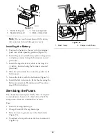
Страница 28: ...instructions 4 Disconnect the negative black ground cable from the battery post Figure 31 Retain all fasteners Incorrect battery cable routing could damage the machine and cables causing sparks Sparks can cause the battery gasses to explode resulting in personal injury Always disconnect the negative black battery cable before disconnecting the positive red cable Always connect the positive red bat...

Страница 29: ...he fasteners removed previously 4 Slide the red terminal boot onto the positive red battery post 5 Secure the battery with the hold down Figure 31 6 Install the left side console Refer the Accessing the Battery procedure in Premaintenance Procedures page 22for instructions Servicing the Fuses The electrical system is protected by fuses It requires no maintenance however if a fuse blows check the c...

Страница 30: ...d or worn replace it immediately with a genuine Toro replacement blade For convenient sharpening and replacement you may want to keep extra blades on hand A worn or damaged blade can break and a piece of the blade could be thrown into the operator s or bystander s area resulting in serious personal injury or death Inspect the blade periodically for wear or damage Replace a worn or damaged blade Be...

Страница 31: ... blades must be replaced if a solid object is hit if the blade is out of balance or the blade is bent To ensure optimum performance and continued safety conformance of the machine use genuine Toro replacement blades Replacement blades made by other manufacturers may result in non conformance with safety standards Hold the blade end using a rag or thickly padded glove Remove the blade bolt curved w...

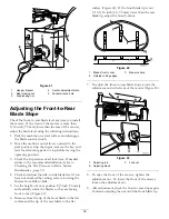
Страница 32: ... 76 mm 5 Carefully rotate the blade s side to side Figure 40 Measure between the outside cutting edges and the flat surface Figure 40 If both measurements are not within 3 16 inch 5 mm an adjustment is required continue with this procedure G005278 1 2 2 3 3 4 4 Figure 40 1 Blades side to side 3 Outside cutting edges 2 Sail area of blade 4 Measure here 6 Measure between the outside cutting edges an...

Страница 33: ...ance page 30 4 Check and adjust the side to side blade level if you have not checked the setting refer to Leveling the Mower from Side to Side 5 Set the height of cut at position 3 3 inch 76 mm and carefully rotate the blades so they are facing front to rear Figure 42 6 Measure from the tip of the front blade to the flat surface and the tip of the rear blade to the flat surface Figure 42 If the fr...

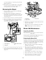
Страница 34: ...45 1 Mower deck 3 Rear lift rod 2 Hanger bracket 6 Slide the mower rearward to remove the mower belt from the engine pulley 7 Slide the mower out from underneath the machine Note Retain all parts for future installation Mower Belt Maintenance Inspecting the Belts Service Interval Every 25 hours Check the belts for wear cracks Check the belts for cracks frayed edges burn marks or any other damage R...

Страница 35: ... belt onto the engine pulley refer to Replacing the Mower Belt Replacing the Grass Deflector An uncovered discharge opening could allow the lawn mower to throw objects in the operator s or bystander s direction and result in serious injury Also contact with the blade could occur Never operate the lawn mower unless you install a cover plate a mulch plate or a grass chute and catcher 1 Locate items ...

Страница 36: ...e the key and wait for all moving parts to stop before leaving the operating position 3 Attach the hose coupling to the end of the mower washout fitting and turn the water on high Figure 48 Note Spread petroleum jelly on the washout fitting O ring to make the coupling slide on easier and protect the O ring Figure 48 1 Washout fitting 3 O ring 2 Hose 4 Coupling 4 Lower the mower to the lowest heigh...

Страница 37: ...ngine Maintenance page 23 4 Grease and oil the machine refer to Lubrication page 22 5 Change the crankcase oil and filter refer to Servicing the Engine Oil in Engine Maintenance page 23 6 Check the tire pressure refer to Checking the Tire Pressure in Drive System Maintenance page 30 7 Charge the battery refer to Servicing the Battery in Electrical System Maintenance page 28 8 Check the condition o...

Страница 38: ...he spark plug s 12 Clean any dirt and chaff from the top of the mower 13 Scrape any heavy buildup of grass and dirt from the underside of the mower then wash the mower with a garden hose 14 Check the condition of the drive and mower belts 15 Check and tighten all bolts nuts and screws Repair or replace any part that is worn or damaged 16 Paint all scratched or bare metal surfaces Paint is availabl...

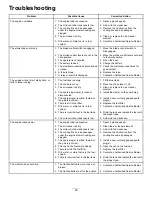
Страница 39: ...n the spark plug 5 The spark plug s is pitted fouled or the gap is incorrect 5 Install a new correctly gapped spark plug s 6 There is dirt in fuel filter 6 Replace the fuel filter 7 Dirt water or stale fuel is in fuel system 7 Contact an Authorized Service Dealer 8 There is incorrect fuel in the fuel tank 8 Drain the tank and replace the fuel with the proper type The engine will not start starts h...

Страница 40: ... the blade s 2 A cutting blade s is are bent 2 Install a new cutting blade s 3 The mower is not level 3 Level the mower from side to side and front to rear 4 An anti scalp wheel is not set correctly 4 Adjust the anti scalp wheel height 5 The underside of the mower is dirty 5 Clean the underside of the mower 6 The tire pressure is incorrect 6 Adjust the tire pressure Uneven cutting height 7 A blade...

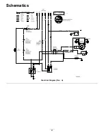
Страница 41: ...Schematics Electrical Diagram Rev A 41 ...

Страница 42: ......

Страница 43: ...cheduled for replacement as required maintenance in the written instructions must be warranted for the warranty period of two years If any such part fails during the period of warranty coverage it must be repaired or replaced by The Toro Company Any such part repaired or replaced under the warranty must be warranted for a time not less than the remaining warranty period B Any warranted part that i...

Страница 44: ...r Division Toro Warranty Company 8111 Lyndale Avenue South Bloomington MN 55420 1196 Toll Free 866 216 6029 U S customers Toll Free 866 216 6030 Canada customers Owner Responsibilities You must maintain your Toro Product by following the maintenance procedures described in the Operator s Manual Such routine maintenance whether performed by a dealer or by you is at your expense Items and Conditions...

Отзывы: