background image

8-11

Digital Edition - TIMECUTTER® HD Service Manual

April 2017

Table of Contents

MOWER DECK

Deck

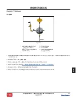
Mower Spindle (Cont.)

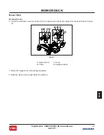
Disassembly

1. Clamp the spindle for service by placing the spindle shaft in a vise.

2. Remove the nut and washer from the top of the pulley (B) (Figure 11).

3. Remove the pulley (B) (Figure 11).

4. Remove spindle housing from the shaft.  

5. Remove the bearing shield (C) (Figure 11).

6. Remove the bearing and the bearing spacer from the top of the spindle housing.

7. Flip over the spindle housing and remove the lower bearing.

8. Inspect the inside of the spindle housing for wear or damage.

A

B

C

D

E

F

G

H

I

Figure 11

A. Spindle Nut

B. Pulley

C. Bearing Shield

D. Spindle Assembly

E. Spindle Mounting Screws

F. Spindle (Apply Anti-Seize)

G. Blade

H. Belleville Washer

I. Blade Bolt

Содержание TIMECUTTER HD 74864

Страница 1: ...R e s i d e n t i a l P r o d u c t s S e r v i c eMa n u a l T I ME C U T T E R H D I s s u e d A p r i l 2 0 1 7 ...

Страница 2: ...f Contents lists the systems and the related topics covered in this manual We are hopeful that you will find this manual a valuable addition to your service shop If you have any questions or comments regarding this manual please contact us at the following address The Toro Company Residential and Landscape Contractor Service Training Department 8111 Lyndale Avenue South Bloomington MN 55420 The To...

Страница 3: ...ed to identify Critical Torque and Fluid Capacity Specifications that are specific to this product and differ from the General Torque Specifications chart given in the Specifications section of this manual or critical fluid capacity values This icon is used to identify Service Interval Reminders throughout this service manual relating to how often a particular part or system of the product should ...

Страница 4: ...on TIMECUTTER HD Service Manual April 2017 Table of Contents Chapters Safety Specifications Maintenance Troubleshooting Chassis Engine Hydrostatic Drive System Mower Deck Electrical 1 1 2 1 3 1 4 1 5 1 6 1 7 1 8 1 9 1 ...

Страница 5: ...1 1 Digital Edition TIMECUTTER HD Service Manual April 2017 Table of Contents Safety SAFETY Table of Contents General Safety Information Think Safety First 1 2 1 2 ...

Страница 6: ...crease in temperature during operation while the unit is running or shortly after it has been running Avoid fires and explosions Avoid spilling fuel and never smoke while working with any type of fuel or lubricant Wipe up any spilled fuel or oil immediately Never remove the fuel cap or add fuel when the engine is running Always use approved labeled containers for storing or transporting fuel and l...

Страница 7: ...ifications Table of Contents General Specifications Unit Dimensions Torque Specifications Standard Torque for Dry Zinc Plated and Steel Fasteners U S Standard Torque for Dry Zinc Plated and Steel Fasteners Metric Equivalents and Conversions U S To Metric Conversions 2 2 2 8 2 9 2 10 2 11 2 13 2 14 ...

Страница 8: ... RPM Spark Plug Champion RN9YC NGK BPR6ES Engine Oil See Viscosity Table in Chapter 3 page 3 6 Oil Capacity 2 4 L 80 oz with Filter Change CARB No EPA Yes Air Filter Standard Fuel Capacity 5 gal Display Hourmeter Battery 12 Volt 195 CCA Clutch Warner 105 ft lbs Clutch Adjustment Non adjustable Hydraulic Drive System Transmission ZT3100 Transmission Lubricant 4 45 L 150 oz Toro HYPR OIL 500 hydraul...

Страница 9: ...203 75211 Front Caster Tires 13x6 5 6 Front Tire Pressure 13 psi Mower Deck Deck Width 48 in 54 in 60 in 48 in Deck Configuration 3 Blade Grade 50 10ga Steel Fabricated Deck Side Discharge Deck Spindles Cast Aluminum with Permanently Lubed Ball Bearings 25 mm spindles Blade Tip Speed 18 880 ft min 18 664 ft min 18 908 ft min 18 880 ft min Cutting Height 1 5 4 5 in 0 25 in increments ...

Страница 10: ...9YC NGK BPR6ES Champion XC12YC Champion RN9YC NGK BPR6ES Engine Oil See Viscosity Table in Chapter 3 page 3 6 Oil Capacity 2 4 L 80 oz with Filter Change 1 9 L 64 oz with Filter Change 2 4 L 80 oz with Filter Change CARB No EPA Yes Air Filter Standard Fuel Capacity 5 gal Display Hourmeter Battery 12 Volt 195 CCA Clutch Warner 105 ft lbs Clutch Adjustment Non adjustable Hydraulic Drive System Trans...

Страница 11: ...2 75213 75210 74864 Front Caster Tires 13x6 5 6 Front Tire Pressure 13 psi Mower Deck Deck Width 54 in 60 in 48 in Deck Configuration 3 Blade Grade 50 10ga Steel Fabricated Deck Side Discharge Deck Spindles Cast Aluminum with Permanently Lubed Ball Bearings 25 mm spindles Blade Tip Speed 18 664 ft min 18 908 ft min 18 880 ft min Cutting Height 1 5 4 5 in 0 25 in increments ...

Страница 12: ...pion RN9YC NGK BPR6ES Engine Oil See Viscosity Table in Chapter 3 page 3 6 Oil Capacity 2 4 L 80 oz with Filter Change CARB No EPA Yes Air Filter Standard Fuel Capacity 5 gal Display Hourmeter Battery 12 Volt 195 CCA Clutch Warner 105 ft lbs Clutch Adjustment Non adjustable Hydraulic Drive System Transmission ZT3100 Transmission Lubricant 4 45 L 150 oz Toro HYPR OIL 500 hydraulic fluid or Mobil 1 ...

Страница 13: ...4865 74866 74867 Front Caster Tires 13x6 5 6 Front Tire Pressure 13 psi Mower Deck Deck Width 54 in 48 in 54 in Deck Configuration 3 Blade Grade 50 10ga Steel Fabricated Deck Side Discharge Deck Spindles Cast Aluminum with Permanently Lubed Ball Bearings 25 mm spindles Blade Tip Speed 18 664 ft min 18 880 ft min 18 664 ft min Cutting Height 1 5 4 5 in 0 25 in increments ...

Страница 14: ...5 2 114 8 34 3 87 1 39 2 99 6 49 7 126 2 794 1747 48 8 124 0 63 4 161 0 49 2 125 0 82 1 208 5 75212 45 2 114 8 34 3 87 1 39 2 99 6 49 7 126 2 808 1778 48 8 124 0 69 3 176 0 55 1 140 0 82 1 208 5 75213 45 2 114 8 34 3 87 1 39 2 99 6 49 7 126 2 830 1826 48 8 124 0 75 4 191 5 61 3 155 7 82 1 208 5 75210 45 2 114 8 34 3 87 1 39 2 99 6 49 7 126 2 744 1637 48 8 124 0 63 4 161 0 49 2 125 0 82 1 208 5 748...

Страница 15: ...n the fastener presence of a prevailing torque feature hardness of the surface underneath of the fastener s head or similar condition which affects the installation As noted in the following tables torque values should be reduced by 25 for lubricated fasteners to achieve the similar stress as a dry fastener Torque values may also have to be reduced when the fastener is threaded into aluminum or br...

Страница 16: ...6 2 22 3 30 3 41 4 43 5 58 7 17 2 18 2 24 3 35 4 47 5 50 6 68 8 7 16 14 UNC 7 16 20 UNF 27 3 27 3 37 4 50 5 68 7 70 7 95 9 29 3 29 3 39 4 55 6 75 8 77 8 104 11 1 2 13 UNC 1 2 20 UNF 30 3 48 7 65 9 75 8 102 11 105 11 142 15 32 4 53 7 72 9 85 9 115 12 120 12 163 16 5 8 11 UNC 5 8 18 UNF 65 10 88 12 119 16 150 15 203 20 210 21 285 28 75 10 95 15 129 20 170 18 230 24 240 24 325 33 3 4 10 UNC 3 4 16 UN...

Страница 17: ...0 10 93 10 126 14 M16 X 2 0 166 17 255 23 229 23 310 31 M20 X 2 5 325 33 440 45 450 46 610 62 NOTE Reduce torque values listed in the table above by 25 for lubricated fasteners Lubricated fasteners are defined as threads coated with a lubricant such as oil graphite or thread sealant such as Loctite Torque values may have to be reduced when installing fasteners into threaded aluminum or brass The s...

Страница 18: ...s Size Threads per Inch Baseline Torque Type A Type B No 6 18 20 20 5 in lb No 8 15 18 30 5 in lb No 10 12 16 38 7 in lb No 12 11 14 85 15 in lb Thread Cutting Screws Zinc Plated Steel Hole size material strength material thickness and finish must be considered when determining specific torque values All torque values are based on non lubricated fasteners Type 1 Type 23 or Type F Thread Size Basel...

Страница 19: ...62 13 64 0 203125 5 159 45 64 0 703125 17 859 7 32 0 21875 5 556 23 32 0 71875 18 256 15 64 0 234375 5 953 47 64 0 734375 18 653 1 4 0 2500 6 350 3 4 0 7500 19 050 17 64 0 265625 6 747 49 64 0 765625 19 447 9 32 0 28125 7 144 25 32 0 78125 19 844 19 64 0 296875 7 541 51 64 0 796875 20 241 5 16 0 3125 7 541 13 16 0 8125 20 638 21 64 0 328125 8 334 53 64 0 828125 21 034 11 32 0 34375 8 731 27 32 0 8...

Страница 20: ...ers 0 0929 Square Inches Square Centimeters 6 452 Acre Hectare 0 4047 Volume Cubic Yards Cubic Meters 0 7646 Cubic Feet Cubic Meters 0 02832 Cubic Inches Cubic Centimeters 16 39 Weight Tons Short Metric Tons 0 9078 Pounds Kilograms 0 4536 Ounces Grams 28 3495 Pressure Pounds Square Inch Kilopascal 6 895 Work Foot Pounds Newton Meters 1 356 Foot Pounds Kilogram Meters 0 1383 Inch Pounds Kilogram Ce...

Страница 21: ...ark Plug Checking the Spark Plug Installing the Spark Plug Cleaning the Cooling System Fuel System Maintenance Replacing the In Line Fuel Filter Electrical System Maintenance Servicing the Battery Belt Maintenance Inspecting the Belts Mower Belt Replacement Hydrostatic Drive Belt Replacement Servicing the Cutting Blades Before Inspecting or Servicing the Blades Inspecting the Blades Checking for B...

Страница 22: ...e After each use Clean the mower deck housing Every 25 hours Clean the air cleaner foam element Check tire pressure Check the belts for wear or cracks Every 100 hours Replace the air cleaner foam element Service the air cleaner paper element Change the engine oil Change the oil filter Check the spark plug s Check the in line fuel filter Every 200 hours Replace the air cleaner paper element Replace...

Страница 23: ...lace the air cleaner foam element Every 200 hours every 2 years whichever comes first Replace the air cleaner paper element More often in dusty dirty conditions Check the air cleaner daily or before starting the engine Check for a build up of dirt and debris around the air cleaner system Keep this area clean Also check for loose or damaged components Replace all bent or damaged air cleaner compone...

Страница 24: ... surface and disengage the PTO Stop the engine wait for all moving parts to stop and remove key Engage the parking brake 2 Clean around the air cleaner cover to prevent dirt from getting into the engine and causing damage 3 Lift the cover and rotate the air cleaner assembly out of the engine Figure 2 and 3 4 Remove the foam element from the paper element Figure 2 Figure 3 ...

Страница 25: ...m element with water NOTE Replace the foam element if it is torn or worn Paper Element 1 Lightly tap the element on a flat surface to remove dust and dirt 2 Inspect the element for tears an oily film and damage to the seal NOTE Do not clean the paper element with pressurized air or liquids such as solvent gas or kerosene Replace the paper element if it is damaged or cannot be cleaned thoroughly ...

Страница 26: ...ce Interval Before each use or daily NOTE Check engine oil level when engine is cold NOTE Do not overfill the crankcase with oil and run the engine engine damage may result 1 Park the machine on a level surface and disengage the PTO Stop the engine wait for all moving parts to stop and remove key Engage the parking brake 2 Make sure the engine is stopped level and is cool so the oil has had time t...

Страница 27: ... oil to the FULL mark on the dipstick Toro 4 Cycle Premium Engine Oil is recommended refer to the following information for an appropriate API rating and viscosity Always check the level with the dipstick before adding more oil Do Not overfill NOTE To prevent extensive engine wear or damage always maintain the proper oil level in the crankcase Never operate the engine with the oil level below the ...

Страница 28: ...irst 5 hours After the first month whichever comes first Every 100 hours Yearly whichever comes first Change the engine oil and oil filter more often in dirty or dusty conditions 1 Park the machine on a level surface and disengage the PTO Stop the engine wait for all moving parts to stop and remove key Engage the parking brake 2 Drain the engine oil Figure 6 Figure 6 A B C D E F G H B G ...

Страница 29: ...ilter Cont 3 Change the oil filter NOTE Ensure that the oil filter gasket touches the engine and then turn the filter an additional turn Figure 7 4 Slowly pour approximately 80 of the specified oil into the filler tube Check the oil level and slowly add the additional oil needed to bring it to the FULL mark Figure 8 B A C D E F Figure 8 Figure 7 B A C D E F 3 4 B B ...

Страница 30: ... remove and install the spark plug Use a gapping tool or feeler gauge to check and adjust the air gap Install a new spark plug if necessary Type Champion RN9YC or equivalent Air Gap 0 030 in 0 76 mm Removing the Spark Plug 1 Park the machine on a level surface and disengage the PTO Stop the engine wait for all moving parts to stop and remove key Engage the parking brake 2 Disconnect the wire from ...

Страница 31: ...roperly A black coating on the insulator usually means the air cleaner is dirty NOTE Do not clean the spark plug s Always replace the spark plug s when it has a black coating worn electrodes an oily film or cracks 2 Check the gap between the center and side electrodes 3 Set the gap to 0 030 in 0 76 mm Figure 9 Installing the Spark Plug 1 Tighten the spark plugs to 20 2 ft lbs 25 30 Nm Figure 10 B ...

Страница 32: ...el surface and disengage the PTO Stop the engine wait for all moving parts to stop and remove key Engage the parking brake 2 Remove the air filter from the engine 3 Remove the engine shroud 4 To prevent debris from entering the air intake install the air filter to the filter base 5 Clean debris and grass from the top of the engine 6 Remove the air filter and install the engine shroud 7 Install the...

Страница 33: ... Every 200 hours Every 2 years whichever comes first Replace the in line fuel filter NOTE Never install a dirty filter if it is removed from the fuel line 1 Park the machine on a level surface and disengage the PTO Stop the engine wait for all moving parts to stop and remove key Engage the parking brake Figure 11 2 Remove the hose clamps at filter A Figure 11 3 Remove the filter B Figure 11 4 Repl...

Страница 34: ...stem Maintenance Servicing the Battery Service Interval Monthly NOTE The battery should be maintained at 12 6 volts or greater A battery that has reached a voltage of 12 2 volts or less is considered discharged and should be recharged 1 Charge the battery for 30 minutes at 10 A 2 Test the battery voltage ...

Страница 35: ...rvice Interval Every 25 hours Replace the belt if it is worn The signs of a worn belt include squealing while the belt is rotating the blades slipping while cutting grass frayed edges burn marks and cracks on the belt Mower Belt Replacement Side Discharge Machines see chapter 8 page 8 4 Hydrostatic Drive Belt Replacement see chapter 7 page 7 9 ...

Страница 36: ...resulting in serious injury or death Trying to repair a damaged blade may result in discontinued safety certification of the product 1 Inspect blades periodically for wear 2 Use care when checking the blades Wrap the blades or wear gloves and use caution when servicing the blades Only replace the blades never straighten or weld them 3 On multi bladed machines take care as rotating one blade can ca...

Страница 37: ...k plugs Inspecting the Blades 1 Inspect the cutting edges Figure 12 2 If the edges are not sharp or have nicks remove and sharpen the blade see Sharpening the Blades chapter 3 page 3 21 3 Inspect the blades especially the curved area 4 If you notice any cracks wear or a slot forming in this area immediately install a new blade Figure 12 NOTE Worn bent or out of balance blades cause vibration that ...

Страница 38: ...rk plugs 3 Rotate the blades so they are perpendicular to the rear of the deck Figure 13 4 Measure from a level surface to the cutting edge position A Figure 13 5 Rotate the blades 180 degrees so the opposite end of the blade is forward 6 Measure from a level surface to the cutting edge of the blades at the same position as step 4 NOTE The difference between the dimensions obtained in steps 4 and ...

Страница 39: ...s bent To ensure optimum performance and continued safety conformance of the machine use genuine Toro replacement blades Replacement blades made by other manufacturers may result in non conformance with safety standards 1 Hold the spindle shaft with a wrench 2 Remove the blade bolt curved washer and blade from the spindle shaft Figure 14 A B C D Figure 14 A Sail Area of the Blade B Blade C Curved ...

Страница 40: ...ion 1 Install the blades curved washers and blade bolts onto the spindle shaft Figure 15 NOTE The curved part of the blade must point upward NOTE Install the curved washer cone toward the bolt head 2 Torque the blade bolts to 105 5 ft lbs 145 7 Nm Figure 15 A B C D A Sail Area of the Blade B Blade C Curved Washer D Blade Bolt ...

Страница 41: ... NOTE The blade retains balance if you remove the same amount of material from both cutting edges 2 Check balance of the blade by putting it on a blade balancer Figure 17 NOTE If the blade stays in a horizontal position the blade is balanced and ready to use 3 If the blade is not balanced file some metal off the end of the sail area only 4 Repeat this procedure until the blade is balanced A Figure...

Страница 42: ...4 1 Digital Edition TIMECUTTER HD Service Manual April 2017 Table of Contents TROUBLESHOOTING Troubleshooting Table of Contents Troubleshooting Table 4 2 ...

Страница 43: ... fuel tank The fuel shut off valve is closed Open the fuel shut off valve The oil level in the crankcase is low Add oil to the crankcase The throttle is not in the correct position Be sure that the throttle control is midway between the slow and fast positions There is dirt in the fuel filter Replace the fuel filter There is dirt water or stale fuel in the fuel system Clean and flush the fuel syst...

Страница 44: ...oughly clean cooling fins and the air passages The mower pulls to the left or right with levers fully forward The tracking needs adjustment Adjust the tracking The tire pressure in the drive tires is not correct Adjust the tire pressure in the drive tires The machine does not drive The bypass valves are not closed tight Tighten the bypass valves The pump belt is worn loose or broken Change the bel...

Страница 45: ...eck belt is off the pulley Install the mower belt on the deck pulley and check the idler pulley idler arm and spring for correct position and function The pump drive belt is worn loose or broken Check the belt tension or install a new belt The idler spring is broken or missing Replace the spring The clutch does not engage The fuse is blown Replace the fuse Check the coil resistance battery charge ...

Страница 46: ...sole Removal Installation Seat TIMECUTTER HD ZX Models Only Removal Installation Seat MyRIDE Platform TIMECUTTER HD MR Models Only Removal Installation Fuel Tank Removal Installation Throttle Control Assembly Removal Installation Choke Control Assembly Removal Installation Park Brake Handle Assembly Removal Installation 5 3 5 4 5 4 5 4 5 5 5 5 5 6 5 6 5 7 5 8 5 8 5 10 5 11 5 11 5 12 5 13 5 13 5 18...

Страница 47: ...gital Edition TIMECUTTER HD Service Manual April 2017 Table of Contents CHASSIS Table of Contents Motion Control Assembly Removal Installation Adjusting the Motion Control Handle Position 5 32 5 32 5 34 5 35 ...

Страница 48: ...5 3 Digital Edition TIMECUTTER HD Service Manual April 2017 Table of Contents CHASSIS Chassis Figure 1 A Caster Fork B Tire and Wheel Asm C Screw Caster Tires Exploded View A C B ...

Страница 49: ...he axle and inspect the inside of the axle bearing area for damage or excessive wear NOTE The bearings are pressed in and cannot be reused Installation 1 Clean the surface inside the axle bearing area keeping surface clean of debris 2 Using a proper bearing installation tool install a new lower bearing from the bottom side into the axle making sure that it is fully seated 3 Using a proper bearing ...

Страница 50: ... the caster wheel away from the caster fork 5 Remove the dust caps felt washers and wheel spanner 6 Remove the bearings bearings may have a slight press fit 7 Install new bearings bearings may have a slight press fit NOTE The bearings are sealed and do not require grease lubrication They may also have a slight press fit 8 Install the spanner into the caster wheel then install felt washers and dust...

Страница 51: ... moving parts to stop and remove key Engage the parking brake 2 Disconnect the battery cables and remove the battery from the tray 3 Remove the three shoulder bolts T30 VERIFY at location A B C Figure 2 4 Remove the fuel cap D and disconnect the keeper line Figure 3 5 Remove the left side control lever 6 Lift the console upward off of the machine 7 Replace the fuel cap Figure 2 Figure 3 A B C D ...

Страница 52: ...ng that it seats properly on the supports Figure 4 3 Install the left side control lever 4 Install the keeper line into the fuel cap and reinstall the fuel cap 5 Install the three shoulder bolts T30 VERIFY at location A B C Figure 5 6 Install the battery onto the battery tray and secure with the bungee strap 7 Connect the battery terminals and verify proper function of the unit Figure 4 Figure 5 A...

Страница 53: ...disengage the PTO Stop the engine wait for all moving parts to stop and remove key Engage the parking brake 2 Disconnect the battery terminals 3 Remove the three shoulder bolts T30 at locations A B C Figure 6 4 Remove the screws securing the control panel assembly to the console Figure 7 5 Remove the right side control lever Figure 6 Figure 7 A B C D ...

Страница 54: ...s Right Console Cont Removal Cont 6 Lift the console upward off of the machine while feeding the control panel assembly through the opening in the console Figure 8 NOTE The control panel assembly should be supported while servicing the machine to avoid damage to cables or wire harness Figure 8 ...

Страница 55: ...eats properly on the supports Figure 9 NOTE Before securing the control panel to the console ensure that all cables and electrical connections are seated firmly in place on the underside of the control panel assembly 2 Secure the control panel assembly to the console 3 Install the three shoulder bolts T30 at location A B C Figure 10 4 Connect the battery terminals and verify proper function of the...

Страница 56: ...y Engage the parking brake 2 Disconnect the battery terminals 3 Disconnect the wire harness connector at the operator presence switch 4 Remove the cotter pins from the stop rod on the left and right sides of the seat 5 Slide the rod toward the inside of the seat pan to release the seat from the frame then slide it the opposite way to release it from the other side 6 Lift the seat assembly off of t...

Страница 57: ...f the frame with the hole in the seat plate 3 Install the stop rod and secure with one cotter pin 4 Slide the rod toward the outside of the machine while aligning the hole on the opposite side with the hole in the frame 5 Insert the stop rod to secure the seat in place and install the cotter pin 6 Raise the seat and connect the wire harness terminal to the operator presence switch 7 Lift and lower...

Страница 58: ...the battery terminals Remove the battery 3 Remove the right and left side consoles see Left Console Removal chapter 5 page 5 6 see Right Console Removal chapter 5 page 5 8 4 Disconnect the wire harness connector at the operator presence switch 5 Remove the relay and bolt attaching relay and fuse to holder on frame A B C D E F G H J I Figure 13 A Seat Asm B Seat Pan C Shock Spring Asm D Floor mat E...

Страница 59: ...al April 2017 Table of Contents CHASSIS Seat MyRIDE Platform TIMECUTTER HD MR Models Only Cont Removal Cont 6 Disconnect the fuel supply line at the fuel filter Figure 14 7 Disconnect the vent line at the splice fitting Figure 15 Figure 15 Figure 14 ...

Страница 60: ...E Platform TIMECUTTER HD MR Models Only Cont Removal Cont 8 Remove the bolt and nut securing the front shock spring assembly to the MyRIDE platform Figure 16 9 Remove the self tapping screw on the frame brackets on each side of the machine A Figure 17 Release the vent hose keepers B Figure 16 Figure 17 A B ...

Страница 61: ...MyRIDE Platform TIMECUTTER HD MR Models Only Cont Removal Cont 10 Remove the two bolts and nuts securing the frame brackets to the main frame on each side of the machine Figure 18 11 Tilt the MyRIDE assembly one way Unhook the fuel line keeper from under the seat Figure 19 Figure 18 Figure 19 ...

Страница 62: ...dels Only Cont Removal Cont 12 Lift the entire MyRIDE assembly up and away from the main frame Removing the MyRIDE assembly will take two or more people NOTE Do not remove either of the swing arm rods from the swing arm underneath the machine This could cause damage or misalignment of the MyRIDE suspension platform Figure 20 Figure 20 ...

Страница 63: ...d properly in the front and rear of the frame and secured with the hold down bolt Figure 21 2 Lower the MyRIDE assembly onto the main frame aligning the frame brackets on each side with the mating holes in the main frame Reconnect the fuel line keeper under the seat 3 Install the two bolts and nuts securing the frame brackets to the main frame on each side of the machine Figure 22 Figure 21 Figure...

Страница 64: ...assis Seat MyRIDE Platform TIMECUTTER HD MR Models Only Cont Installation Cont 4 Install the self tapping screw on the frame bracket on each side of the machine Figure 23 5 Install the bolt and nut securing the front shock spring assembly to the MyRIDE Platform Figure 24 Figure 23 Figure 24 ...

Страница 65: ...he fuel supply line to the fuel filter 8 Connect the vent line keepers to the vent lines 9 Connect the wire harness terminal to the operator presence switch 10 Install the relay and fuse holder 11 Install the right and left side consoles see Left Console Installation chapter 5 page 5 7 see Right Console Installation chapter 5 page 5 10 12 Install the battery and connect the battery terminals 13 Ve...

Страница 66: ...sole Removal chapter 5 page 5 6 see Right Console Removal chapter 5 page 5 8 4 Re install the fuel cap 5 Remove the seat assembly for ZX models or the MyRIDE Platform Assembly for MR models see Seat TIMECUTTER HD ZX Models Only Removal chapter 5 page 5 11 see Seat MyRIDE Platform TIMECUTTER HD MR Models Only Removal chapter 5 page 5 13 6 Remove the fuel tank hold down rod and bolt A Figure 25 7 Di...

Страница 67: ...l tank hold down rod and bolt A Figure 26 5 Install the seat assembly see Seat TIMECUTTER HD ZX Models Only Installation chapter 5 page 5 12 see Seat MyRIDE Platform TIMECUTTER HD MR Models Only Installation chapter 5 page 5 18 6 Install the right and left consoles see Left Console Installation chapter 5 page 5 7 see Right Console Installation chapter 5 page 5 10 7 Install the fuel cap by sliding ...

Страница 68: ...ng brake 2 Disconnect the battery 3 Remove the control panel assembly from the right console Figure 27 4 Pry the keeper tab on the throttle control assembly and unsnap the control from the console 5 Loosen the clamp securing the throttle cable to the throttle plate Figure 28 6 Remove the throttle cable from the throttle plate noting the position of the cable in the plate 7 Pull the throttle cable ...

Страница 69: ...tle Control Assembly Cont Installation 1 Route the throttle cable through the right console Figure 29 2 Snap the throttle control assembly into place 3 Install the control panel assembly into the console 4 Move the throttle control lever to the full speed position Figure 30 Figure 29 Figure 30 ...

Страница 70: ...throttle cable in the throttle plate on the engine in the position previously noted 6 Place the cable under the cable clamp 7 Ensure that the throttle control lever is in the fast idle position Figure 31 NOTE Pull on the cable and verify the engine is at full throttle then tighten the clamp 8 Connect the battery terminals and verify proper function of the unit Figure 31 ...

Страница 71: ...the battery 3 Loosen the clamp securing the choke cable to the choke plate on the engine Figure 32 4 Remove the choke cable from the plate noting the position of the cable in the plate 5 Remove the control panel assembly from the right console 6 On the bottom side of the control panel assembly loosen the jam nut securing the choke lever in place Remove the nut from the choke cable 7 Pull the choke...

Страница 72: ...he choke cable through the control panel assembly 2 Thread the jam nut over the choke cable up to the control panel assembly Figure 33 3 Attach the choke cable assembly to the control panel with the jam nut 4 Install the control panel assembly into the console 5 Move the choke control lever to the open position down Figure 34 Figure 33 Figure 34 ...

Страница 73: ... Cont 6 Place the z bend of the choke cable in the choke plate on the engine in the position previously noted 7 Place the cable under the cable clamp 8 Ensure that the choke control lever is pressed down fully and tighten the cable clamp Figure 35 9 Connect the battery terminals and verify proper function of the unit Figure 35 ...

Страница 74: ...y terminals 3 Remove the left side console see Left Console Removal chapter 5 page 5 6 4 Re install the fuel cap 5 Remove the locking cotter pin A securing the intermediate brake rod B Figure 36 to the park brake lever 6 Remove the bolt and flange nut G from the park brake lever assembly Retain the bushing D and wave spring E Figure 36 A B C D E F G Figure 36 A Cotter Pin B Intermediate Brake Rod ...

Страница 75: ...and through the park brake handle Figure 37 NOTE Verify alignment before tightening misalignment can damage the wave washer Figure 38 Park Brake Hardware Orientation A B C D E Figure 37 Figure 38 A Screw B Washer C Wave Washer D Flange Pivot E Flange Nut A B C D E F G A Cotter Pin B Intermediate Brake Rod C Torx Screw D Flange Bushing E Wave Spring F Brake Flanged Bushing G Flange Nut ...

Страница 76: ...e oriented as shown install the bolt through the brake detent B Figure 39 and connect the flange nut Torque to 200 25 in lbs 23 3 Nm 3 Install the intermediate brake rod and secure with locking cotter pin 4 Cycle the park brake lever to ensure that it locks in the engaged position 5 Connect the battery terminals and verify proper function A B Figure 39 A Torx Screw B Brake Detent ...

Страница 77: ...e unit so that the drive wheels are off the ground NOTE The console must be removed for access see Left Console Removal chapter 5 page 5 6 see Right Console Removal chapter 5 page 5 8 3 Remove the two bolt securing the motion control handle to the motion control assembly A Figure 40 4 Disconnect the motion control damper from the motion control assembly B Figure 40 5 Disconnect the motion control ...

Страница 78: ...Digital Edition TIMECUTTER HD Service Manual April 2017 Table of Contents CHASSIS Chassis Motion Control Assembly Cont Removal Cont 6 Disconnect the motion control assembly from the frame Figure 41 Figure 41 ...

Страница 79: ...rol assembly to the frame 3 Connect the motion control linkage to the motion control assembly 4 Connect the motion control damper to the motion control assembly 5 Connect the motion control handle to the motion control assembly using the two bolts 6 Adjust the neutral setting see Hydrostatic Drive Transmission chapter 7 page 7 13 7 Lower the unit and verify proper function 8 Adjust the tracking if...

Страница 80: ... the engine wait for all moving parts to stop and remove key 2 Move the levers into the operating position 3 Loosen the two bolts that secure the motion control handles to the motion control assembly A Figure 42 4 Align the levers front to back and secure the bolts Figure 42 5 Move the levers into the park position 6 Verify proper function of the unit NOTE Motion control levers may be adjusted up ...

Страница 81: ...ce Manual April 2017 Table of Contents ENGINE Engine Table of Contents Engine Mounting Toro Twin Cylinder Engine Exploded View Toro Twin Cylinder Engine Removal Installation Kawasaki Engine Removal Installation 6 2 6 3 6 3 6 6 6 11 6 11 6 12 ...

Страница 82: ...2 Digital Edition TIMECUTTER HD Service Manual April 2017 Table of Contents ENGINE Engine Mounting Toro Twin Cylinder Engine Exploded View A B C D Figure 1 A Engine B Muffler C Flat Washer D Taptite Screw ...

Страница 83: ...ngine wait for all moving parts to stop and remove key Engage the parking brake 2 Disconnect the battery 3 Remove the engine guard 4 Remove the muffler 5 Remove the mower belt see Mower Belt Removal chapter 3 page 3 15 6 Remove the hydrostatic drive belt see Hydrostatic Drive Belt Removal chapter 7 page 7 9 7 Disconnect the chassis wire harness from the main engine wire harness Figure 2 Figure 2 ...

Страница 84: ...CUTTER HD Service Manual April 2017 Table of Contents ENGINE Toro Twin Cylinder Engine Cont Removal Cont 8 Disconnect the red wire from the starter Figure 3 9 Disconnect the black engine ground wire Figure 4 Figure 3 Figure 4 ...

Страница 85: ... splice with Toro supplied hose Figure 6 12 Disconnect the throttle cable see Throttle Control Assembly Removal chapter 5 page 5 23 13 Disconnect the choke cable see Choke Control Assembly Removal chapter 5 page 5 26 14 Remove the clutch mounting bolt and washer Slide the clutch off of the crankshaft 15 Remove the engine pulley 16 Remove the engine mounting bolts 17 Lift the engine away from the f...

Страница 86: ...les of the engine base to the frame and attach the two rear mounting bolts and two flat washers loosely NOTE Apply Loctite 243 to engine mounting bolts 4 Attach the front bolt through the clutch anchor and into the engine base Figure 7 5 Install the three remaining engine bolts 6 Torque the four engine mounting bolts to 450 50 in lbs 52 5 8 Nm 7 Apply anti seize to the clutch end of the crankshaft...

Страница 87: ...chor Figure 8 9 Install the washer E and clutch bolt F Figure 8 NOTE Apply Loctite to the clutch bolt F Figure 8 10 Torque the clutch bolt to 50 60 ft lbs 69 83 Nm 11 Connect the choke cable see Choke Control Assembly Installation chapter 5 page 5 27 12 Connect the throttle cable see Throttle Control Assembly Installation chapter 5 page 5 24 Figure 8 A Engine Pulley B Clutch Stop C PTO Clutch D Cl...

Страница 88: ... Manual April 2017 Table of Contents ENGINE Toro Twin Cylinder Engine Cont Installation Cont 13 Connect the black engine ground wire Figure 9 NOTE Apply Loctite to ground bolt 14 Connect the red wire to the starter Figure 10 Figure 10 Figure 9 ...

Страница 89: ... Contents ENGINE Engine Toro Twin Cylinder Engine Cont Installation Cont 15 Connect the chassis wire harness to the main engine wire harness Figure 11 16 Connect the fuel supply line to the fuel pump 17 Connect the vent line to barb splice Figure 12 Figure 11 Figure 12 ...

Страница 90: ...mower belt see Mower Belt Replacement chapter 3 page 3 15 20 Install the muffler and new exhaust gaskets NOTE Torque muffler mounting bolts or nuts to 150 170 in lbs 17 20 Nm 20 Install the engine guard 21 Fill crankcase with approved oil and verify proper oil level 22 Connect the battery terminals 23 Lower the unit and verify proper function NOTE Verify Engine speed is set to proper RPM specifica...

Страница 91: ...t Removal chapter 7 page 7 9 7 Disconnect the chassis wire harness from the main engine wire harness 8 Disconnect the red wire from the starter Figure 13 9 Disconnect the black engine ground wire 10 Disconnect the fuel supply line at the fuel pump 11 Remove vent line at splice with Toro supplied hose 12 Disconnect the throttle cable see Throttle Control Assembly Removal chapter 5 page 5 23 13 Disc...

Страница 92: ...three engine bolts 6 Torque the four engine mounting bolts to 300 400 in lbs 34 46 Nm 7 Apply anti seize to the clutch end of the crankshaft 8 Install the engine pulley onto the crankshaft 9 Install the clutch on to the crankshaft ensuring that the slot in the clutch aligns with the tab on the clutch anchor 10 Install the washer and clutch bolt as shown NOTE Apply Loctite to clutch bolt 11 Torque ...

Страница 93: ...rostatic drive belt see Hydrostatic Drive Belt Installation chapter 7 page 7 11 20 Install the mower belt see Mower Belt Replacement chapter 3 page 3 15 21 Install the muffler and new exhaust gaskets NOTE Torque muffler mounting bolts or nuts to 150 170 in lbs 17 20 Nm 22 Install the engine guard 23 Fill crankcase with approved oil and verify proper oil level 24 Connect the battery terminals 25 Lo...

Страница 94: ...tic Drive Exploded View Using the Drive Wheel Release Valves Bypass Valves Neutral Adjustment Tracking Adjustment Hydro Change Procedure Purging Procedure Hydrostatic Drive Belt Removal Installation Hydrostatic Drive Transmission Removal Right Side Shown Installation Right Side Shown 7 2 7 3 7 4 7 6 7 7 7 8 7 9 7 9 7 11 7 13 7 13 7 17 ...

Страница 95: ...F E C D B A A N M L K I J Figure 1 A Breather Tube B RH Hydro Assembly C RH Bypass Lever D Idler Arm E Idler Spring F Pulley Idler G Pulley Idler H Hydrostatic Drive Belt I Rear Hydro Support J Rear Guard K LH Bypass Lever L LH Hydro Assembly M Wheel Lug Nuts N Hydro Cross Plate Hydrostatic Drive Exploded View ...

Страница 96: ...moving parts to stop and remove key Engage the parking brake 2 Locate the bypass levers on the frame on both sides of the engine 3 Move the bypass lever forward through the key hole and down to lock them in place Figure 2 Do this for each bypass lever 4 Disengage the parking brake before pushing the machine Do not start the machine 5 To operate the machine normally move the bypass levers to the re...

Страница 97: ...e off the ground 3 Unplug the seat switch on the bottom side of the seat and install a temporary jumper wire across the plug connector wire harness side 4 Start the engine and allow the machine to warm up for 3 5 minutes 5 Disengage the parking brake 6 Move the motion control levers into the neutral position 7 Increase the engine speed to full throttle Observe the movement of the rear drive wheels...

Страница 98: ...trol rod clockwise or counterclockwise until the drive wheel is slightly rotating in reverse or not rotating at all Repeat for both drive wheels if necessary Figure 3 NOTE When the unit is in neutral the stud should be roughly centered in the slot of the control plate Figure 4 9 Stop the engine and lower the unit 10 Verify proper neutral setting and tracking Figure 3 Figure 4 ...

Страница 99: ...cks or pulls to the RIGHT Turn the LH adjustment nut 1 full turn CLOCKWISE If more adjustment is needed turn the adjustment nut 1 full turn at a time Figure 5 If the unit tracks or pulls to the LEFT Turn the RH adjustment nut 1 full turn CLOCKWISE If more adjustment is needed turn the adjustment nut 1 full turn at a time Figure 5 Figure 5 ...

Страница 100: ... Remove the top port plug A Figure 6 5 Remove the breather hose and fill vent located on the top of the hydro 6 Fill approximately 2 qts of Toro HYPR OIL 500 or 20W 50 engine oil to the level of the top port plug hole 7 Re install the top port plug A Figure 6 8 Re install the breather hose 9 Perform purging procedure see Purging Procedure chapter 7 page 7 8 Figure 6 A B A Top Port Plug B Breather ...

Страница 101: ...d of operation High operating temperature and excessive expansion of oil in the latter case oil level may be high in the expansion tank or overflow The following procedure should be performed with the vehicle wheels off the ground and then repeated under operating conditions 1 With the bypass valve open push position and the engine running slowly move the directional controls forward reverse lever...

Страница 102: ...parts to stop and remove key Engage the parking brake 2 Raise and support the unit so that the drive wheels are off the ground 3 Remove the mower belt from the clutch see Mower Belt Replacement chapter 3 page 3 15 4 Using a spring removal tool Toro Part No 92 5771 remove the drive idler spring from the slot in the frame Remove the spring from the drive idler arm and inspect for damage or wear Figu...

Страница 103: ...IC DRIVE SYSTEM Hydrostatic Drive Belt Cont Removal Cont 6 Remove the rear pulley A Figure 8 7 Remove the idler arm and pulley B Figure 8 8 Remove the drive belt from the hydrostatic drive pulleys NOTE Inspect the belt for excessive wear damage or cracking replace if necessary Figure 8 A B ...

Страница 104: ...Belt Cont Installation 1 Route the hydrostatic drive belt around the two transmission pulleys 2 Route the drive belt around the engine pulley 4 Install the idler arm and pulleys A Figure 9 NOTE Make sure that the belt is properly routed before installation 5 Install the clutch stop 6 Verify proper routing of the belt Figure 9 A ...

Страница 105: ... the idler arm loop and use a spring removal tool to secure the spring A into the slot on the right rear of the frame Figure 10 NOTE Ensure proper orientation with hook openings facing away from the idler pivot 5 Install the mower belt onto the clutch see Mower Belt Replacement chapter 3 page 3 15 6 Lower the unit 7 Connect the battery and check for proper operation Figure 10 A ...

Страница 106: ...of the same steps apply to the left side hydrostatic drive transmission 1 Stop the engine wait for all moving parts to stop and remove key Engage the parking brake 2 Disconnect the battery cables 3 Raise and support the unit so that the drive wheels are off the ground 4 Remove the drive wheel s 5 Remove the drive belt see Hydrostatic Drive Belt Removal chapter 7 page 7 9 6 Disconnect the motion co...

Страница 107: ...ROSTATIC DRIVE SYSTEM Hydrostatic Drive Transmission Cont Removal Right side shown Cont 7 Disconnect the bypass arm Figure 12 8 Disconnect the lower brake linkage from the transmission Figure 13 9 Disconnect the connectors securing the overflow tube to the chassis Figure 12 Figure 13 ...

Страница 108: ...able of Contents HYDROSTATIC DRIVE SYSTEM Drive Hydrostatic Drive Transmission Cont Removal Right side shown Cont NOTE Overflow tubes should stay connected to the top of the transmission To avoid oil leaking keep the overflow tubes oriented up Figure 14 Figure 14 ...

Страница 109: ... mounting bolts 12 Loosen the two bolts connecting the transmission to the rear cross member D Figure 14 13 Remove the front mounting bolt C Figure 14 14 Support the transmission and remove the mounting hardware Lower the transmission Figure 15 A Front Inner Mounting Bolts to Frame Bracket B Bottom Mounting Bolts to Cross Plate C Front Mid Mounting Bolts to Frame Bracket D Rear Mid Mounting Bolts ...

Страница 110: ... transmission A Figure 15 Do not tighten at this time 3 Install the rear hydro mounting bolts and nuts D Figure 15 and the front mounting bolt and nut Do not tighten at this time NOTE The proper torque sequence as outlined below is critical in avoiding damage to the hydrostatic transmissions and the frame 4 Tighten the front mounting bolt through the frame bracket C Figure 15 5 Tighten the hydro c...

Страница 111: ...IVE SYSTEM Hydrostatic Drive Transmission Cont Installation Right side shown Cont 8 Remove the protective cap from the hydraulic oil nipple install the overflow tube and move the hose clamps into place Figure 17 9 Connect the lower brake linkage to the transmission Figure 18 Figure 17 Figure 18 ...

Страница 112: ...rive Transmission Cont Installation Right side shown Cont 10 Connect the bypass arm Figure 19 11 Connect the motion control linkage Figure 20 12 Install the drive belt see Hydrostatic Drive Belt Installation chapter 7 page 7 11 13 Install the drive wheel and torque the lug nuts to 80 10 ft lbs 110 14 Nm Figure 19 Figure 20 ...

Страница 113: ...t plugs Figure 21 15 Follow the purging procedure to remove all air from the system see Purging Procedure chapter 7 page 7 8 16 Adjust the neutral setting if necessary see Hydrostatic Drive Belt Installation chapter 7 page 7 11 17 Lower the unit and verify proper function 18 Adjust the tracking if necessary see Tracking Adjustment chapter 7 page 7 6 19 Connect the battery terminals and verify prop...

Страница 114: ...Exploded View Deck Lift Assembly Exploded View Mower Belt Replacement Mower Deck Removal Installation Mower Spindle Removal Installation Disassembly Assembly Leveling the Mower Deck Servicing the Cutting Blades Electric PTO Clutch Removal Installation 8 2 8 3 8 4 8 6 8 6 8 8 8 10 8 10 8 10 8 11 8 12 8 13 8 16 8 17 8 17 8 18 ...

Страница 115: ...iew K L H J I M N O P Q F E D C B A G Figure 1 A Mower Deck B Cut Off Baffle C Spindle Housing D Spindle E Blade F Blade Bolt G Anti Scalp Roller H Deflector Discharge I Pulley Spindle J Bearing Shield K Right Belt Cover L Left Belt Cover M Belt Guide Idler N Mower Belt O Pulley Idler P Idler Spring Q Idler Arm ...

Страница 116: ...Deck Lift Assembly Exploded View E B G F D H J A I C K Figure 2 A Height of Cut Transport Lock B Height of Cut Plate C Pivot Arm Rear D Pivot Arm Front E Height of Cut Pin F Deck Lift Chain G Deck Pivot Rod H Deck Pivot Pan I Deck Lift Assist Spring J Height of Cut Link K Deck Lift Assist Pedal ...

Страница 117: ...wer deck to the 3 in 76 mm height of cut position 4 Remove the bolts from the covers and lift covers off the deck Figure 3 5 Using a spring removal tool Toro Part No 92 5771 remove the spring tension from the idler pulley Figure 4 6 Lower the deck to the lowest height of cut position and secure the pin to lock in position 7 Remove the belt from the deck pulleys and the clutch pulley E D C B A 1 2 ...

Страница 118: ... deck pulleys Figure 5 9 Install the idler spring using the spring removal tool 10 Ensure that the belt is properly seated in all pulleys 11 Install the belt covers Figure 6 NOTE Torque the belt cover bolts to 50 75 in lbs 6 8 Nm 12 Tighten the bolts to secure the cover to the deck 13 Connect the battery terminals and verify proper function of the unit Figure 6 Figure 5 ...

Страница 119: ...ing parts to stop and remove key Engage the parking brake 2 Disconnect the battery terminals 3 Remove the height adjustment pin and lower the deck to the ground 4 Remove the mower belt see Mower Belt Replacement chapter 3 page 3 15 5 Remove the two hairpins and washers that secure the link pin to the frame and deck then remove the link pin Figure 7 A B C Figure 7 A Link Pin B Washer C Hairpin Cott...

Страница 120: ...eck Removal Cont 6 Lift the mower deck to remove tension from the chains and unhook the chains from the deck lift arms Figure 8 7 Raise the height of cut to the transport position 8 Slide the deck out from underneath the machine A B C D A B C D Figure 8 A Deck Lift Arm B Chain C Hook D Adjustment Bolt ...

Страница 121: ...sition and secure with the height of cut pin 3 Lift the rear of the mower deck and attach the chains to the rear lift arms Figure 9 4 Attach the front chains to the front deck lift arms 5 Install the link pin through the frame hanger and the deck Secure with hairpins and washers that were previously removed Figure 10 A A B B C C D D Figure 9 Figure 10 A B C A Link Pin B Washer C Hairpin Cotter A D...

Страница 122: ... pulley first then onto the mower deck see Mower Belt Replacement chapter 3 page 3 15 7 Install the mower belt covers Torque the belt cover bolts to 50 75 in lbs 6 8 Nm 8 Raise the deck to the 3 in 76 mm height of cut position and check for deck level see Leveling the Mower Deck chapter 8 page 8 13 9 Connect the battery terminals and verify proper function of the unit ...

Страница 123: ...e spindle assembly downward through the deck Installation 1 Position the spindle against the deck and align the mounting holes NOTE Ensure that the underside of the deck is clean before proceeding with the spindle installation 2 Install six spindle mounting bolts Torque to 150 25 in lbs 17 3 Nm NOTE Spindle mounting screws are thread forming Do not reuse spindle mounting screws 3 Install the belle...

Страница 124: ...lley B Figure 11 4 Remove spindle housing from the shaft 5 Remove the bearing shield C Figure 11 6 Remove the bearing and the bearing spacer from the top of the spindle housing 7 Flip over the spindle housing and remove the lower bearing 8 Inspect the inside of the spindle housing for wear or damage A B C D E F G H I Figure 11 A Spindle Nut B Pulley C Bearing Shield D Spindle Assembly E Spindle Mo...

Страница 125: ...p the spindle housing over and install the bearing spacer B Figure 12 4 Press the lower bearing C Figure 12 into the spindle housing by pressing equally on the inner and outer race NOTE The inner and outer race on the upper bearing must be supported while installing the lower bearing 5 Apply anti seize to the spindle shaft and install the spindle shaft 6 Flip the spindle over while supporting the ...

Страница 126: ...oving parts to stop and remove key 2 Disconnect the battery terminals 3 Check to ensure that all tires are properly inflated and adjust as necessary 4 Lock the mower deck in the transport position 5 Rotate the blades so that they are parallel to the rear of the deck Figure 13 A B B B C C C C C Figure 13 A Blades Side to Side B Outside Cutting Edge C Measure from the tip of the blade to the flat su...

Страница 127: ...ts are not within 3 16 in 5 mm an adjustment is required 7 Rotate the blades so that they are perpendicular to the rear of the deck Figure 14 If the front blade tip is not 1 6 7 9 mm 1 16 5 16 in lower than the rear blade tip continue with Leveling the Mower Deck A A A B B B C C C C C C Figure 14 A Blades Side to Side B Outside Cutting Edge C Measure from the tip of the blade to the flat surface h...

Страница 128: ... lever to the 3 in 76 mm position 10 Place two 6 6 mm 2 5 8 in thickness blocks under the front edge of the cutting deck skirt one on each side of the cutting deck but not under the anti scalp roller brackets 11 Place two 7 3 mm 2 7 8 in thickness blocks under each side of the rear edge of the deck one on each side of the deck Figure 15 A B C Figure 15 A Wood Block 6 6 cm 2 5 8 in thick B Wood Blo...

Страница 129: ...14 Tighten the four leveling adjustment bolts 15 Re check that the blocks fit snugly under the deck skirt and that all attachment bolts are tight 16 Verify that the front to rear blade slope is within tolerance The front blade tip should be between 1 16 5 16 in 1 6 7 9 mm lower than the rear blade tip to a flat surface 17 Recheck the level of the blades and repeat deck leveling procedure if necess...

Страница 130: ...ttery terminals 3 Raise and support the unit so that the drive wheels are off the ground 4 Remove the mower belt see Mower Belt Replacement chapter 3 page 3 15 5 Disconnect the clutch wire connector from the clutch 6 Remove the clutch mounting bolt and washers Slip the clutch off of the crankshaft A B C D E F Figure 17 A Engine Pulley to Shaft Apply Anti Seize B Bolt Clutch Stop Mount C Clutch Sto...

Страница 131: ...the rubber isolator is in place Figure 18 NOTE Apply anti seize to the end of the pulley shaft 2 Apply thread lock to the clutch bolt 3 Install the washer and clutch mounting bolt F Figure 18 Torque the clutch bolt to 55 5 ft lbs 76 7 Nm 4 Connect the clutch power wire to the clutch Figure 18 A B C D E F A Engine Pulley to Shaft Apply Anti Seize B Bolt Clutch Stop Mount C Clutch Stop D Clutch Isol...

Страница 132: ...2017 Table of Contents MOWER DECK Deck Electric PTO Clutch Cont Installation Cont NOTE Ensure wire harness is properly routed to avoid contact with the mower belt Figure 19 5 Connect the battery terminals 6 Lower the unit and verify proper function Figure 19 ...

Страница 133: ...tions Testing Hourmeter Testing Operator Presence Switch Seat Switch Testing Neutral Switch Left and Right Parking Brake Switch Starter Solenoid Testing PTO Switch Testing Electric PTO Clutch Testing Coil Resistance Measurement PTO Clutch Continuity to Ground Check Measuring Clutch Current Draw TVS Diode Kill Relay Electrical Schematic 9 2 9 3 9 4 9 4 9 5 9 5 9 6 9 7 9 7 9 8 9 8 9 9 9 10 9 11 9 11...

Страница 134: ...ystem Exploded View Figure 1 A B E C D H G H I M P O J F L N K P A Ignition Key B Ignition Switch C PTO Switch D Hourmeter E 12V Power Port F Wire Harness G Solenoid H Neutral Switches I Park Brake Switch J Clutch Connector K Fuse Block L Battery M Engine Connector N Kill Relay O Engine Ground P B Wire ...

Страница 135: ...4 volts or less are considered discharged Check that all engine and chassis ground wires are securely connected and not damaged 3 Use of test lights and continuity testers may result in false readings and lead to an incorrect diagnosis 4 Occasionally electrical testing requires the use of a jumper wire to bypass a safety interlock switch allowing the technician to continue troubleshooting by takin...

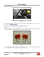
Страница 136: ...lways use Toro fuses when replacing a damaged or blown fuse Testing 1 Visual Inspection The fuses used in this application may be visually inspected A failed fuse can be identified by a broken or melted element inside the fuse cover or a damaged spade Figure 3 2 Using a digital multi meter set to the OHM or Continuity setting check the continuity between the fuse blades If the fuse is OPEN no cont...

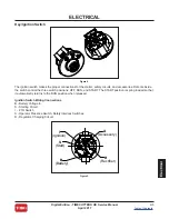
Страница 137: ...tents inside the switch control the three switch positions OFF RUN and START The START position is spring loaded so that it automatically returns to the RUN position when released Ignition Switch Wiring Connections B Battery Voltage In S Starting Circuit I PTO Switch A Operator Presence Switch Safety Interlock Switches R Regulator Charging Circuit Figure 4 Ignition I Start S Battery B Rectifier R ...

Страница 138: ...ntly rock the connector back and forth until unplugged 3 Using a digital multi meter set to the OHM or Continuity setting verify that continuity exists between the terminals listed for each switch position 4 Using a digital multi meter set to the OHM or Continuity setting verify that NO continuity exists between the terminals not listed for each switch position Position Circuit Make 1 OFF None 2 R...

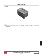
Страница 139: ...ents ELECTRICAL Electrical Hourmeter The hourmeter records hours of operation when the ignition key is ON and the PTO switch is ON Testing 1 With the ignition switch in the RUN position and the PTO switch closed ON verify battery voltage and ground to the hourmeter Figure 6 ...

Страница 140: ...and neutral switches NOTE The operator presence switch is part of the seat assembly Testing 1 Disconnect the wire harness from the Operator Presence Switch located on the bottom of the seat assembly 2 Using a digital multi meter set to the OHM or Continuity setting test the continuity between the two switch terminals When the seat is vacated the switch should NOT have continuity open When the oper...

Страница 141: ... a single pole plunger type switch normally open with two terminals When the plunger is depressed the circuit closes and there is continuity between the terminals Motion Control Levers in neutral position OUT the switch should have continuity closed Motion Control Levers in the operating position IN the switch should NOT have continuity open Figure 8 ...

Страница 142: ...normally open and normally closed When the parking brake is set engaged the normally closed pole of the switch is open and the normally open pole is closed This allows proper voltage and ground signal path for the safety interlock and PTO operations Parking Brake ON the switch should have continuity closed Parking Brake OFF the switch should NOT have continuity open Figure 9 Figure 10 ...

Страница 143: ...rned to START The solenoid protects the ignition switch from the high current drawn by the starter motor Testing 1 Disconnect the solenoid from the wiring harness 2 With a multi meter set to the OHM or Continuity setting check to ensure that terminals C and D are open no continuity Figure 12 3 Apply 12 volts DC to terminal A and ground terminal B Terminals C and D should now be closed continuity F...

Страница 144: ...ock system the PTO switch will prevent the engine from cranking starting when in the ON position by preventing the starter solenoid from grounding through the kill relay NOTE The engine will not crank over when the PTO switch is in the ON position The PTO Switch provides battery voltage from the ignition switch to the parking brake switch and the neutral switches as part of the safety interlock sy...

Страница 145: ...al multi meter set to the OHM or Continuity setting verify the following Pin 2 and 5 should have continuity closed Pin 1 and 4 should have continuity closed Pin 1 and 7 should NOT have continuity open Pin 2 and 8 should NOT have continuity open 5 With the switch in the OFF position button pushed IN Pin 1 and 7 should have continuity closed Pin 2 and 8 should have continuity closed Pin 1 and 4 shou...

Страница 146: ...e is the only piece that moves vertically on the crankshaft It is normally spring loaded so that it is not in contact with the clutch plate and is pressed against the brake material opposite the clutch plate When power is applied the friction plate is pulled toward the clutch plate and the two rotate as one When the clutch plate and the friction plate rotate as different speeds it is known as clut...

Страница 147: ...ngage the PTO Stop the engine wait for all moving parts to stop and remove the key Engage the parking brake 2 Disconnect the clutch wire connector 3 Set the multi meter to measure resistance OHMs setting 4 Connect the meter lead wires to the terminals in the clutch connector 5 See the PTO Clutch Electrical Specifications chart Resistance OHMs AMP Draw Continuity to Ground 3 05 5 3 93 OPEN Figure 1...

Страница 148: ...parking brake 2 Disconnect the clutch wire connector 3 Set the multi meter to measure resistance OHM setting 4 Connect one multi meter lead to the engine chassis or battery ground Connect the other multi meter lead to each of the clutch connector terminals 5 The two clutch connector terminals should never have continuity to ground and should OPEN at all times 6 If continuity is found between the P...

Страница 149: ... for all moving parts to stop and remove the key Engage the parking brake 2 Disconnect the clutch wire connector 3 Set the multi meter to measure amps 10 amp scale 4 Connect the positive meter lead to the chassis harness terminal A 5 Connect the negative meter lead to the corresponding wire terminal B 6 Connect a short jumper lead from terminal C to terminal D 7 Turn the ignition switch to RUN and...

Страница 150: ...tects the electrical system from current surges caused by PTO engagement and disengagement Testing No testing procedure available If the diode is suspected to be faulty replace the diode If the system fuse blows each time the clutch is engaged the TVS diode is more than likely shorting clutch power to ground Figure 18 ...

Страница 151: ...RICAL Electrical Kill Relay The Kill Relay grounds the magneto when the key is turned to the OFF position When the key is turned to the RUN position the solenoid is grounded and the magneto is no longer grounded The Kill Relay prevents starting in an unsafe position Figure 19 Figure 20 ...

Страница 152: ...87a KILL RELAY 85 P03 3 4 5 P03 1 2 126 2601 PTO CLUTCH L01 P06 B P06 A BT01 TBD TERMINAL TERMINAL BATTERY 32160 022 ATC ATO FUSE HOLDER B P17 A 32160 022 ATC ATO FUSE HOLDER B P18 A F01 25A 109102 CHARGE FUSE SP01 SW06 82 2190 SEAT SWITCH P02 2 P02 1 D01 100 4918 FLYBACK DIODE 31P B 31P A DIS03 120 2244 HR HOUR METER P15 2 P15 1 J04 P23 A B ACCESSARY CONNECTOR IGNITION SWITCH LEGEND SP03 F02 15A ...

Страница 153: ...R e s i d e n t i a l P r o d u c t s ...

Отзывы: