background image

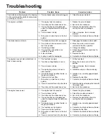
Problem

Possible Cause

Corrective Action

1. The bypass valves are open.

1. Close the tow valves.

2. The traction belts are worn, loose, or

broken.

2. Contact an Authorized Service Dealer.

3. The traction belts are off the pulleys.

3. Contact an Authorized Service Dealer.

The machine does not drive.

4. The transmission has failed.

4. Contact an Authorized Service Dealer.

1. The cutting blade(s) is/are bent or

unbalanced.

1. Install new cutting blade(s).

2. The blade mounting bolt is loose.

2. Tighten the blade mounting bolt.

3. The engine mounting bolts are loose.

3. Tighten the engine mounting bolts.

4. The engine pulley, idler pulley, or blade

pulley is loose.

4. Tighten the appropriate pulley.

5. The engine pulley is damaged.

5. Contact an Authorized Service Dealer.

6. The blade spindle is bent.

6. Contact an Authorized Service Dealer.

The machine vibrates abnormally.

7. The motor mount is loose or worn.

7. Contact an Authorized Service Dealer.

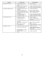
1. The blade(s) is not sharp.

1. Sharpen the blade(s).

2. A cutting blade(s) is/are bent.

2. Install a new cutting blade(s).

3. The mower is not level.

3. Level the mower from side-to-side and

front-to-rear.

4. An anti-scalp roller (if applicable) is not

set correctly.

4. Adjust the anti-scalp wheel height.

5. The underside of the mower deck is

dirty.

5. Clean the underside of the mower

deck.

6. The tire pressure is incorrect.

6. Adjust the tire pressure.

The cutting height is uneven.

7. A blade spindle is bent.

7. Contact an Authorized Service Dealer.

1. The drive belt is worn, loose or broken.

1. Install a new drive belt.

2. The drive belt is off of the pulley.

2. Install the drive belt and check the

adjusting shafts and belt guides for the
correct position.

3. The power-takeoff (PTO) switch or

PTO clutch is faulty.

3. Contact an Authorized Service Dealer.

The blades do not rotate.

4. The mower belt is worn, loose, or

broken.

4. Install a new mower belt.

53


Содержание TimeCutter 5000C

Страница 1: ...rm No 3433 630 Rev C TimeCutter 5000C or 5475C Riding Mower Model No 75753 Serial No 400000000 and Up Model No 75757 Serial No 400000000 and Up Register at www Toro com Original Instructions EN 3433 630 C ...

Страница 2: ...ther reproductive harm Introduction This rotary blade riding lawn mower is intended to be used by homeowners in residential applications It is designed primarily for cutting grass on well maintained lawns Using this product for purposes other than its intended use could prove dangerous to you and bystanders Read this information carefully to learn how to operate and maintain your product properly ...

Страница 3: ...e Side Discharge 24 Adjusting the Height of Cut 25 Adjusting the Anti Scalp Rollers 25 Operating Tips 26 After Operation 27 After Operation Safety 27 Pushing the Machine by Hand 27 Transporting the Machine 28 Maintenance 30 Maintenance Safety 30 Recommended Maintenance Schedule s 30 Pre Maintenance Procedures 32 Raising the Machine 32 Lubrication 32 Greasing the Bearings 32 Engine Maintenance 33 E...

Страница 4: ...ly people who are responsible trained familiar with the instructions and physically capable to operate or service the machine Do not operate the machine near drop offs ditches embankments water or other hazards or on slopes greater than 15 Do not put your hands or feet near moving components of the machine Do not operate the machine without all guards safety switches and other safety protective de...

Страница 5: ...rees Use the slope chart to determine the degree of slope of hills before operating Do not operate this machine on a slope greater than 15 degrees Fold along the appropriate line to match the recommended slope 2 Align this edge with a vertical surface a tree building fence pole etc 3 Example of how to compare slope with folded edge 5 ...

Страница 6: ...dness or severe burns 4 Wear eye protection 9 Flush eyes immediately with water and get medical help fast 5 Read the Operator s Manual 10 Contains lead do not discard decaloemmarkt Manufacturer s Mark 1 This mark indicates that the blade is identified as a part from the original machine manufacturer decal93 7009 93 7009 1 Warning do not operate the mower with the deflector up or removed keep the d...

Страница 7: ...ng parts 2 Thrown object hazard raised baffle do not operate the machine with an open deck use a bagger or a baffle 4 Entanglement hazard keep away from moving parts keep all guards and shields in place decal133 8062 133 8062 decal138 2456 138 2456 1 Read the Operator s Manual 3 Do not overfill the fuel tank 2 Park the machine on a level surface when filling the fuel tank decal139 2388 139 2388 1 ...

Страница 8: ...9 2394 1 Traction controls 4 Neutral 2 Fast 5 Reverse 3 Slow 6 Parking brake decal139 2395 139 2395 1 Parking brake 4 Neutral 2 Fast 5 Reverse 3 Slow 6 Traction controls Decal 139 2397 is for models with MyRide Only decal139 2397 139 2397 8 ...

Страница 9: ...emberment hazard of the hand mower blade entanglement hazard of the hand belt stay away from moving parts keep all guards and shields in place 5 Tipping hazard do not use dual ramps when loading onto a trailer use 1 ramp wide enough for the machine use a ramp with a slope less than 15 back up the ramp when loading the machine and drive forward off the ramp when unloading 7 Tipping hazard do not us...

Страница 10: ...eration for the machine 1 Warning read the Operator s Manual 4 Runover hazard do not carry passengers look behind you when moving in reverse 2 Cutting dismemberment hazard of hand mower blade entanglement hazard of hand belt stay away from moving parts keep all guards and shields in place 5 Tipping hazard when loading onto a trailer do not use dual ramps only use a singular ramp wide enough for th...

Страница 11: ...e 4 Motion control levers 7 Deck lift pedal 10 Rear drive wheel 2 Operator seat 5 Front caster wheel 8 Height of cut lever 11 Control panel 3 Fuel tank cap 6 Smart Speed lever 9 Deflector 12 MyRide adjustment lever machines with MyRide only 11 ...

Страница 12: ...igure 5 Models without MyRide 1 Deck lift pedal 4 Motion control levers 7 Fuel tank cap 10 Deflector 2 Smart Speed lever 5 Control panel 8 Anti scalp roller 3 Height of cut lever 6 Engine 9 Front caster wheel 12 ...

Страница 13: ... mower blades Figure 6 Motion Control Levers Use the motion control levers to drive the machine forward reverse and turn either direction Figure 4 Park Position Move the motion control levers outward from the center to the PARK position when exiting the machine Figure 21 Always position the motion control levers into the PARK position when you stop the machine or leave it unattended MyRide Adjustm...

Страница 14: ...gulations may restrict the age of the operator The owner is responsible for training all operators and mechanics Inspect the area where you will use the machine and remove all objects that could interfere with the operation of the machine or that the machine could throw Become familiar with the safe operation of the equipment operator controls and safety signs Check that operator presence controls...

Страница 15: ...tainer opening at all times until fueling is complete Do not use a nozzle lock open device If you spill fuel on your clothing change your clothing immediately Do not overfill the fuel tank Replace the fuel cap and tighten it securely Clean grass and debris from the cutting unit muffler drives grass catcher and engine compartment to help prevent fires Clean up oil or fuel spills Adding Fuel Recomme...

Страница 16: ...e PARK position and you rise from the seat Testing the Safety Interlock System Test the safety interlock system before you use the machine each time If the safety system does not operate as described below have an Authorized Service Dealer repair the safety system immediately 1 Sit on the seat move the motion control levers in the PARK position and move the blade control switch to the ON position ...

Страница 17: ...ions for reference The following graphic shows the position for a soft or firm ride and the different detent positions Figure 11 1 Park the machine on a level surface disengage the blade control switch and move the motion control levers outward to the PARK position 2 Shut off the engine remove the key and wait for all moving parts to stop before leaving the operating position 3 Step off the machin...

Страница 18: ... to the OFF position the engine should shut off and the blade should stop If not stop using your machine immediately and contact an Authorized Service Dealer Operate the machine only in good visibility and appropriate weather conditions Do not operate the machine when there is the risk of lightning Keep your hands and feet away from the cutting units Keep clear of the discharge opening Do not mow ...

Страница 19: ...d shut off the machine if children enter the operating area Before backing up or turning the machine look down and all around for small children Do not carry children on the machine even when the blades are not moving Children could fall off and be seriously injured or prevent you from safely operating the machine Children who have been given rides in the past could appear in the operating area wi...

Страница 20: ...istance twice the width of the machine between the machine and any hazard 3 Water Towing Safety Do not attach towed equipment except at the hitch point Do not use the machine as a towing vehicle unless it has a hitch installed Do not exceed the weight limits for towed equipment and towing on slopes The towed weight must not exceed the weight of the machine and operator Never allow children or othe...

Страница 21: ... the PTO g187517 Figure 18 Operating the Choke Use the choke to start a cold engine 1 Pull up the choke knob to engage the choke before using the key switch Figure 19 Note Ensure that you fully engage the choke You may need to hold the knob up when you use the key switch 2 Push down the choke to disengage the choke after the engine has started Figure 19 g295540 Figure 19 1 ON position 2 OFF positi...

Страница 22: ...ol switch to the OFF position Figure 17 2 Move the motion control levers outward to the PARK position 3 Move the throttle lever to the SLOW position and let the engine idle for 1 minute 4 Turn the key to the OFF position and remove the key CAUTION Children or bystanders may be injured if they move or attempt to operate the machine while it is unattended Always remove the key and engage the parking...

Страница 23: ...r damage to the machine Use caution when making turns Slow the machine down before making sharp turns Driving Forward Note Always use caution when backing up and turning 1 Move the levers to the center unlocked position 2 To go forward slowly push the motion control levers forward Figure 22 g008952 Figure 22 Driving Backward 1 Move the levers to the center unlocked position 2 To go backward slowly...

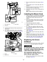
Страница 24: ...lows Normal mowing Moving the machine Using the Side Discharge The mower has a hinged grass deflector that disperses clippings to the side and down toward the turf DANGER Without a grass deflector discharge cover or a complete grass catcher assembly mounted in place you and others are exposed to blade contact and thrown debris Contact with rotating mower blade s and thrown debris will cause injury...

Страница 25: ...ollers Whenever you change the height of cut adjust the height of the anti scalp rollers Note Adjust the anti scalp rollers so that the rollers do not touch the ground in normal flat mowing areas 1 Park the machine on a level surface disengage the blade control switch and move the motion control levers outward to the PARK position 2 Shut off the engine remove the key and wait for all moving parts ...

Страница 26: ... the same cutting height mow more often in early spring As the grass growth rate slows in mid summer mow less frequently If you cannot mow for an extended period first mow at a high cutting height then mow again 2 days later at a lower height setting Using a Slower Cutting Speed To improve cut quality use a slower ground speed in certain conditions Avoiding Cutting Too Low When mowing uneven turf ...

Страница 27: ...st be in the RUN position The battery needs to be charged and functioning to disengage the electric brake Pushing the Machine 1 Park the machine on a level surface disengage the blade control switch and move the motion control levers outward to the PARK position 2 Shut off the engine remove the key and wait for all moving parts to stop before leaving the operating position 3 Locate the bypass leve...

Страница 28: ...p you or bystanders avoid injury Refer to your local ordinances for trailer and tie down requirements WARNING Driving on the street or roadway without turn signals lights reflective markings or a slow moving vehicle emblem is dangerous and can lead to accidents causing personal injury Do not drive the machine on a public street or roadway Selecting a Trailer WARNING Loading a machine onto a traile...

Страница 29: ...ontrol or a tip over situation 1 If using a trailer connect it to the towing vehicle and connect the safety chains 2 If applicable connect the trailer brakes and lights 3 Lower the ramp ensuring that the angle between the ramp and the ground does not exceed 15 degrees Figure 28 4 Back the machine up the ramp Figure 29 g027995 Figure 29 1 Back the machine up the ramp 2 Drive the machine forward dow...

Страница 30: ...enever you raise the machine Keep all parts in good working condition and all hardware tightened especially the blade attachment hardware Replace all worn or damaged decals Disconnect the battery before repairing the machine Disconnect the negative terminal first and the positive last Connect the positive terminal first and the negative last To ensure optimum performance use only genuine Toro repl...

Страница 31: ...ge the battery and disconnect the battery cables Perform all maintenance procedures listed above before storage Paint any chipped surfaces CAUTION If you leave the key in the switch someone could accidently start the engine and seriously injure you or other bystanders Shut off the engine and remove the key from the switch before you perform any maintenance 31 ...

Страница 32: ...s Grease the caster wheel bearings Grease Type No 2 lithium grease 1 Park the machine on a level surface disengage the blade control switch and move the motion control levers outward to the PARK position 2 Shut off the engine remove the key and wait for all moving parts to stop before leaving the operating position 3 Clean the grease fittings Figure 32 with a rag Note Scrape any paint off the fron...

Страница 33: ...osition 2 Shut off the engine remove the key and wait for all moving parts to stop before leaving the operating position 3 Clean around the air cleaner cover to prevent dirt from getting into the engine and causing damage 4 Loosen the hose clamp and remove the paper element Figure 33 g207139 Figure 33 1 Cover 3 Hose clamp 2 Paper element Servicing the Paper Air Cleaner Element Service Interval Eve...

Страница 34: ...moving parts to stop before leaving the operating position Note Ensure that the engine is cool so that the oil has had time to drain into the sump 3 To keep dirt grass clippings etc out of the engine clean the area around the oil fill cap and dipstick before removing it Figure 35 g194611 Figure 35 Changing the Engine Oil Service Interval After the first 8 hours Change the engine oil Every 100 hour...

Страница 35: ...anging the Engine Oil Filter Service Interval Every 200 hours Change the engine oil filter more often in dirty or dusty conditions 1 Drain the oil from the engine refer to Changing the Engine Oil page 34 2 Change the engine oil filter Figure 38 g027477 Figure 38 Note Ensure that the oil filter gasket touches the engine and then turn the oil filter an extra 3 4 turn 3 Fill the crankcase with the pr...

Страница 36: ... Figure 39 g027478 Figure 39 Checking the Spark Plug Important Do not clean the spark plug s Always replace the spark plug s when it has a black coating worn electrodes an oily film or cracks If you see light brown or gray on the insulator the engine is operating properly A black coating on the insulator usually means the air cleaner is dirty Set the gap to 0 75 mm 0 03 inch g206628 Figure 40 Inst...

Страница 37: ...autions Replacing the In Line Fuel Filter Service Interval Every 100 hours Replace the in line fuel filter Never install a dirty filter after removing it from the fuel line 1 Park the machine on a level surface disengage the blade control switch and move the motion control levers outward to the PARK position 2 Shut off the engine remove the key and wait for all moving parts to stop before leaving ...

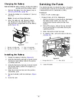
Страница 38: ...he blade control switch and move the motion control levers outward to the PARK position 2 Shut off the engine remove the key and wait for all moving parts to stop before leaving the operating position 3 Raise the seat to access the battery 4 Disconnect the negative black ground cable from the battery post Figure 43 Note Retain all fasteners WARNING Incorrectly removing the cables from battery coul...

Страница 39: ...rminal 3 Using the fasteners previously removed install the negative battery cable to the negative battery terminal 4 Slide the red terminal boot onto the positive red battery post 5 Secure the battery with the hold down Figure 43 6 Lower the seat Servicing the Fuses The electrical system is protected by fuses It requires no maintenance however if a fuse blows check the component circuit for a mal...

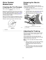
Страница 40: ...ts 1 Turn the key to the OFF position or disconnect the battery 2 Locate the shaft on the electric brake where the brake link arms are connected Figure 47 3 Rotate the shaft forward to release the brake g294417 Figure 47 1 Brake link arm on the electric brake control module 2 Left rear tire Adjusting the Tracking When driving the machine forward full speed across a flat level surface if the machin...

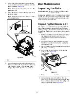
Страница 41: ...ades slipping while cutting grass and frayed edges burn marks and cracks on the belt Replacing the Mower Belt The signs of a worn belt include squealing while the belt is rotating blades slipping while cutting grass and frayed edges burn marks and cracks on the belt Replace the mower belt if any of these conditions are evident 1 Park the machine on a level surface disengage the blade control switc...

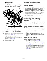
Страница 42: ...i bladed machines take care as rotating one blade can cause other blades to rotate Replace worn or damaged blades and bolts in sets to preserve balance Servicing the Cutting Blades To ensure a superior quality of cut keep the blades sharp For convenient sharpening and replacement keep extra blades on hand Before Inspecting or Servicing the Blades 1 Park the machine on a level surface disengage the...

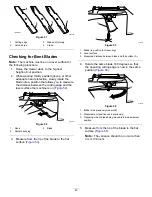
Страница 43: ...ine is on Figure 52 g014972 Figure 52 1 Deck 3 Blade 2 Spindle housing 3 Measure from the tip of the blade to the flat surface Figure 53 g014973 Figure 53 1 Blade in position for measuring 2 Level surface 3 Measured distance between blade and the surface A 4 Rotate the same blade 180 degrees so that the opposing cutting edge is now in the same position Figure 54 g014974 Figure 54 1 Blade side prev...

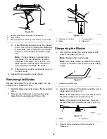
Страница 44: ... blade is out of balance or bent 1 Hold the blade end using a rag or thickly padded glove 2 Remove the blade bolt curved washer and blade from the spindle shaft Figure 56 g027833 Figure 56 1 Sail area of the blade 3 Curved washer 2 Blade 4 Blade bolt Sharpening the Blades 1 Use a file to sharpen the cutting edge at both ends of the blade Figure 57 Note Maintain the original angle Note The blade re...

Страница 45: ...ng the operating position 3 Set the height of cut to 76 mm 3 inches 4 Carefully rotate the blades side to side 5 Measure between the outside cutting edges and the flat surface Figure 59 Note If both measurements are not within 5 mm 3 16 inch an adjustment is required refer to Leveling from Side to Side page 46 g296913 Figure 59 1 Blades side to side 3 Measure from the tip of the blade to the flat ...

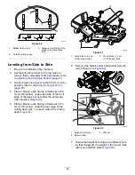
Страница 46: ...thickness of 6 6 cm 2 5 8 inches under each side of the front edge of the deck but not under the anti scalp roller brackets Figure 61 5 Place 2 blocks each having a thickness of 7 3 cm 2 7 8 inches under the rear edge of the cutting deck skirt 1 on each side of the cutting deck Figure 61 g298028 Figure 61 1 Wood block 6 6 cm 2 5 8 inches thick 2 Wood block 7 3 cm 2 7 8 inches thick 6 Remove the ha...

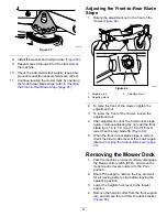
Страница 47: ...nt of the mower loosen the adjustment nut 4 After adjustment check the front to rear slope again continue adjusting the nut until the front blade tip is 1 6 to 7 9 mm 1 16 to 5 16 inch lower than the rear blade tip Figure 64 5 When the front to rear blade slope is correct check the side to side level of the mower again refer to Checking the Side to Side Level page 45 Removing the Mower Deck 1 Park...

Страница 48: ... leaving the operating position 3 Slide the mower under the machine 4 Lower the height of cut lever to the lowest position 5 On 1 side of the machine lift the rear of the mower deck and install the lift arm to the deck pin Figure 66 6 Install the lift arm using the washer and hairpin cotter Figure 66 7 Repeat steps 5 and 6 for the other side of the machine 8 Attach the front support rod to the mow...

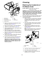
Страница 49: ...ice Interval After each use Clean the mower deck housing Important You can wash the machine with a mild detergent and water Do not pressure wash the machine Avoid excessive use of water especially near the control panel under the seat around the engine hydraulic pumps and motors Wash the underside of the mower deck after each use to prevent grass buildup for improved mulch action and clipping disp...

Страница 50: ... where there is an open flame spark or pilot light such as on a water heater or on other appliances Cleaning and Storage 1 Park the machine on a level surface disengage the blade control switch PTO and move the motion control levers outward to the PARK position 2 Shut off the engine remove the key and wait for all moving parts to stop before leaving the operating position 3 Remove grass clippings ...

Страница 51: ...he oil inside the cylinder Install the spark plug s Do not install the wire on the spark plug s 14 Check and tighten all fasteners Repair or replace any part that is damaged 15 Paint all scratched or bare metal surfaces Paint is available from your Authorized Service Dealer 16 Store the machine in a clean dry garage or storage area Remove the key from the switch and keep it out of reach of childre...

Страница 52: ...2 Move the choke lever to the ON position 3 The air cleaner is dirty 3 Clean or replace the air cleaner element 4 The spark plug wire s is loose or disconnected 4 Install the wire s on the spark plug 5 The spark plug s is pitted fouled or the gap is incorrect 5 Install a new correctly gapped spark plug s 6 There is dirt in fuel filter 6 Replace the fuel filter 7 Dirt water or stale fuel is in fuel...

Страница 53: ...ne vibrates abnormally 7 The motor mount is loose or worn 7 Contact an Authorized Service Dealer 1 The blade s is not sharp 1 Sharpen the blade s 2 A cutting blade s is are bent 2 Install a new cutting blade s 3 The mower is not level 3 Level the mower from side to side and front to rear 4 An anti scalp roller if applicable is not set correctly 4 Adjust the anti scalp wheel height 5 The underside ...

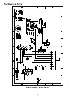
Страница 54: ...Schematics g307974 Electrical Diagram 139 2356 Rev A 54 ...

Страница 55: ...Notes ...

Страница 56: ...to restaurants grocery stores hotels schools and hospitals and on a wide variety of products Additionally some online and mail order retailers provide Prop 65 warnings on their websites or in catalogs How do the California warnings compare to federal limits Prop 65 standards are often more stringent than federal and international standards There are various substances that require a Prop 65 warnin...

Отзывы: