TDC+ QUICK START GUIDE
Page 4
/ 20
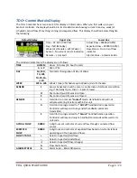
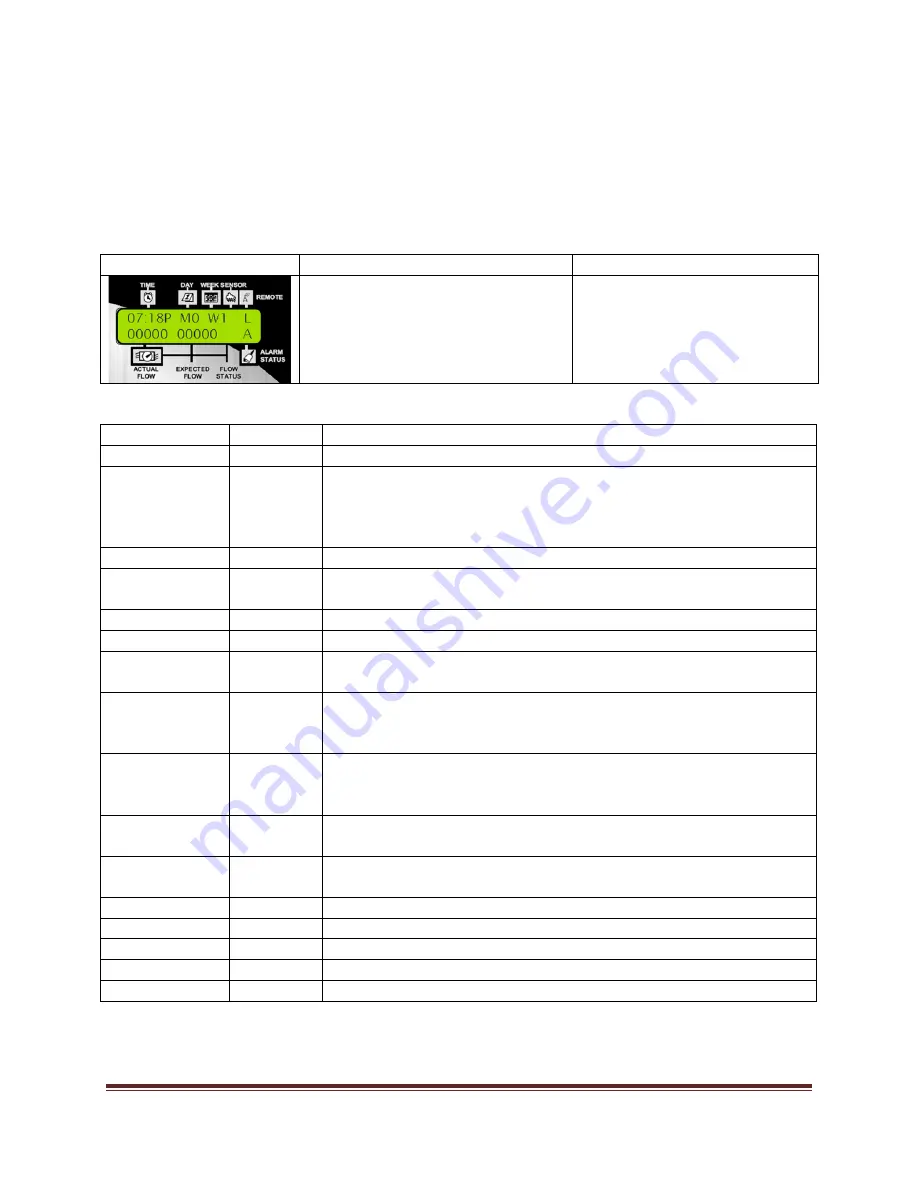
TDC+ Control Module Display
The
TDC+
Controller
has
a
two
‐
line
LCD
for
display
of
information.
When
you
first
walk
up
to
your
Sentinel
controller,
the
display
should
be
in
its
standard
mode
showing
current
time,
day,
week
(of
schedule),
actual
flow
(if
anything
running)
and
expected
flow.
This
display
should
look
something
like
the
following:
Default
Display
Upper
Line
Lower
Line
Time
–
07:18
P
(7:18
PM)
Day
–
MO
(Monday)
Week
(of
schedule)
–
W1
(Week
1)
Sensor
–
No
current
sensor
indication
Remote
–
L
(Locked)
Actual
Flow
–
00000
(0
GPM)
Expected
Flow
–
00000
(0
GPM)
Flow
Status
–
No
current
flow
indicator
Alarm
Status
–
A
(Alarm
Exists)
The
standard
indicators
in
the
display
are
as
follows:
TIME
HH:MM
Hours
:
Minutes
(12
‐
hour
format)
A
or
P
AM
or
PM
DAY
SU,
MO,
TU,
WE,
TH,
FR,
SA,
or
SU
Two
‐
letter
Designation
of
Day
of
Week
WEEK
W1
to
W6
Week
1
(one)
of
Schedule
up
to
Week
6
(six)
of
Schedule
SENSOR
1
Sensor
Activated
‐
Switch
sensor
is
in
alternate
of
its
Normal
condition.
E.g.
If
Normally
Open,
then
1
=
Sensor
Closed.
O
Dry
contact
(switch)
sensor
is
Open
C
Dry
contact
(switch)
sensor
is
Closed
REMOTE
L
Field
Unit
is
in
remote
“Locked”
mode.
Hand
held
radio
will
not
activate
watering
functions
within
this
unit.
A
Field
Unit
is
programmed
for
“All
Call”
handheld
radio
operation.
Controller
will
respond
to
any
and
all
handheld
commands
transmitted.
S
Field
Unit
is
programmed
for
“Secure”
handheld
radio
operation.
Controller
will
respond
only
to
handheld
commands
addressed
to
its
unit
code.
ACTUAL
FLOW
00000
5
‐
digit
numeric
indicator
of
current
flow
through
connected
flow
sensor
EXPECTED
FLOW
00000
5
‐
digit
numeric
indicator
of
expected
flow
based
on
current
stations
operating
and
their
expected
flows.
FLOW
STATUS
+
Actual
>
Expected
(Overflow)
‐‐
Actual
<
Expected
(Underflow)
:)
Actual
=
Expected
(Flow
is
happy)
A
Flow
Alarm
Exists
ALARM
STATUS
A
Alarm
Exists
–
Blank
Otherwise


