

10
SECTION 4: TRACTOR SET-UP
In the event your tractor was crated with the steering
wheel removed for shipping reasons, use the following
instructions to properly assemble the parts.
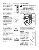
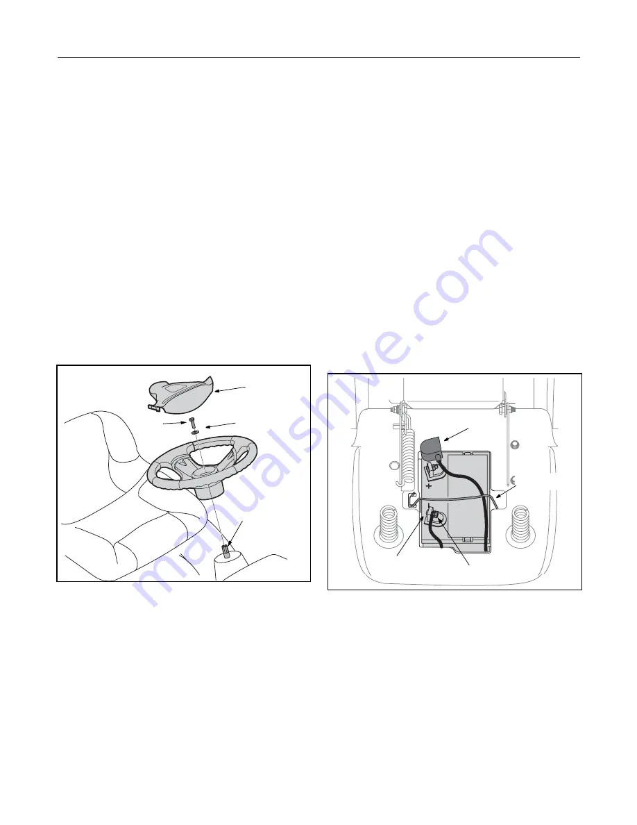
Attaching The Steering Wheel
In the event your tractor was crated with the steering
wheel and the seat removed for shipping reasons, use
the following instructions to properly assemble the
parts.
Tools Required
(1) 1/2" socket wrench
1.
The hardware for attaching the steering wheel has
been packed within the steering wheel, beneath
steering wheel cap. Carefully pry off the steering
wheel cap and remove the hardware.
2.
With the wheels of the tractor pointing straight
forward,
place the steering wheel over the steering
shaft.
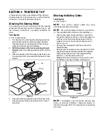
3.
Place the washer (with the cupped side down) over
the steering shaft and secure with the hex bolt. See
Figure 1.
Figure 1
4.
Place the steering wheel cap over the center of the
steering wheel and push downward until it “clicks”
into place.
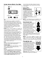
Attaching the Battery Cables
Tools Required
(1) 7/16" wrench
NOTE:
Your tractor’s battery cables may have
already be attached at the factory.
NOTE:
The positive battery terminal is marked Pos.
(+). The negative battery terminal is marked Neg. (–).
•
The positive cable (heavy red wire) is secured to
the positive battery terminal (+) with a carriage bolt
and hex nut at the factory. Make certain that the
rubber boot covers the terminal to help protect it
from corrosion.
•
Remove the carriage bolt and hex nut from the
negative cable.
•
Remove the black plastic cover, if present, from the
negative battery terminal and attach the negative
cable (heavy black wire) to the negative battery
terminal (–) with the bolt and hex nut.
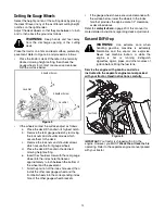
•
Make certain the hold-down rod is in position over
the battery, securing it in place. See Figure 2.
Figure 2
NOTE:
If the battery is put into service after the date
shown on top/side of battery, charge the battery as
instructed
on
page
23
of this manual prior to operating
the tractor.
Cap
Washer
Hex Bolt
Steering Shaft
Hex Nut
Carriage Bolt
Rubber
Boot
Hold Down Rod
Содержание SL500
Страница 29: ...29 ELECTRIC SCHEMATIC ...


