


g028218
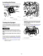
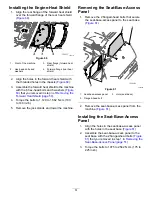
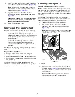
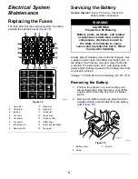
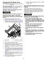
Figure 73
1.
Vent plug
2.
Top of fuel/water separator
6.
Turn the key in the starter switch to the O
N
position.
Note:
The electric fuel pump will begin forcing
air out around the vent plug. Leave the key in
the O
N
position until a solid stream of fuel flows
out around the vent plug.
7.
Tighten the vent plug (
) and turn the
starter switch to the O
FF
position.
8.
Align the drain pan under the fuel-injection pump
portion of the engine (
).
g028217
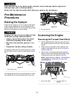
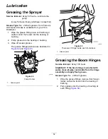
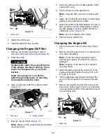
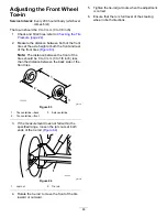
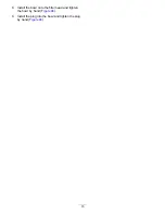
Figure 74
1.
Bleed screw (fuel-injection pump)
9.
Open the air-bleed screw at the fuel-injection
pump (
).
10.
Turn the key in the starter switch to the O
N
position.
Note:
Electric fuel pump will begin operation,
thereby forcing air out around air-bleed screw on
the fuel-injection pump.
11.
Leave the key in the O
N
position until a solid
stream of fuel flows out around the air-bleed
screw (
).
12.
Tighten the air-bleed screw (
) and turn
the key to the O
FF
position.
Note:
Normally, the engine should start after you
bleed the fuel system. However, if the engine does not
start, there may be air trapped between the injection
pump and the injectors; refer to
.
Bleeding Air from the
Injectors
You should perform this procedure only after you have
purged the air in the fuel system and the engine does
not start; refer to
Bleeding the Fuel System (page 58)
.
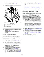
1.
Align a drain pan under the right side of the
engine
2.
Loosen the tube nut at the No. 1 fuel-injector
nozzle and holder assembly.
3.
Move the throttle to the F
AST
position.
4.
Turn the key in the key switch to the S
TART
position and watch the fuel flow around the
connector.
5.
Turn the key to the O
FF
position when you
observe a solid flow of fuel.
6.
Tighten the tube nut.
7.
Clean residual fuel from area around the fuel
injector.
8.
Repeat steps
through
for the remaining
fuel-injector nozzles.
9.
Install the forward heat shield; refer to
the Engine-Heat Shield (page 51)
.
59
Содержание Multi Pro 5800-D
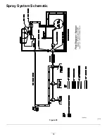
Страница 74: ...Spray System Schematic g034336 Figure 95 74 ...
Страница 89: ...Notes ...
Страница 90: ...Notes ...


