Greensmaster 3320/3420
Page 7 -- 19
Chassis
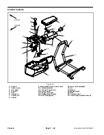
Raise Tank Mount Plate Assembly (Fig. 16)
1. Park machine on a level surface, engage the parking
brake, lower the cutting units and stop the engine. Re-
move key from the ignition switch.
2. Locate and remove four (4) screws that secure tank
mount plate to frame.
3. Carefully lift tank mount plate assembly (hydraulic
reservoir, fuel tank and tank mount plate) up from ma-
chine. Take care to not damage fuel lines, hydraulic
hoses or electrical components as assembly is raised.
Support mount plate assembly in a raised position to al-
low access to machine components.
4. If additional clearance below the tank mount plate
assembly is desired, the suction hose can be clamped
and disconnected from the gear pump:
A. Clamp suction hose to prevent draining the hy-
draulic tank.
B. Thoroughly clean junction of suction hose and
gear pump inlet fitting.
C. Disconnect suction hose from gear pump inlet fit-
ting.
D. Carefully raise and support the tank mount plate
assembly.
5. After completing service work below the tank mount
plate assembly, carefully lower assembly to machine
frame. Secure assembly to frame with removed screws.
If suction hose was disconnected from gear pump, con-
nect hose to pump fitting and secure with hose clamp.
Remove Tank Mount Plate Assembly (Fig. 16)
1. Park machine on a level surface, engage the parking
brake, lower the cutting units and stop the engine. Re-
move key from the ignition switch.
2. Completely drain hydraulic oil from hydraulic reser-
voir through gear pump suction hose into a suitable con-
tainer.
3. Disconnect hydraulic hoses from fittings on hydraulic
tank. Put clean caps or plugs on hoses and fittings.
4. Close fuel shut off valve on fuel tank.
5. Disconnect additional fuel system hoses:
A. On Greensmaster 3320 machines, disconnect
hose from fuel filter that is located next to rear cylin-
der head (Fig. 17). Also, disconnect fuel evaporative
system hoses as needed to allow tank mount plate to
be removed from machine (see Fuel Evaporative
Control System in Chapter 3 -- Gasoline Engine).
B. On Greensmaster 3420 machines, disconnect
fuel supply hose from shut off valve on fuel tank and
fuel return hose from hose splicer fitting above radia-
tor. Also, remove vent hose from grommet in engine
support.
6. If machine is equipped with the Turf Guardian
TM
Leak Detector System, disconnect wire harness con-
nectors from oil level sensor and solenoid coil.
7. Remove four (4) screws that secure tank mount plate
to frame.
8. Lift tank mount plate assembly (hydraulic reservoir,
fuel tank and tank mount plate) from machine.
9. After completing service work below the tank mount
plate assembly, install assembly to machine:
A. Carefully position tank mount plate assembly to
machine frame. Secure assembly to frame with re-
moved screws.
B. Connect and secure all hydraulic hoses (see Hy-
draulic Hose and Tube Installation in the General In-
formation section of Chapter 5 -- Hydraulic System).
C. Connect and secure all fuel hoses. Open fuel
shut off valve on fuel tank.
D. If machine is equipped with the Turf Guardian
TM
Leak Detector System, connect wire harness con-
nectors to oil level sensor and solenoid coil.
E. Fill hydraulic reservoir with new hydraulic oil.
Figure 17
1. Fuel filter
2. Rear cylinder head
1
2
Chas
sis
Содержание Greensmaster 3420 TriFlex
Страница 2: ...Greensmaster 3320 3420 This page is intentionally blank ...
Страница 4: ...Greensmaster 3320 3420 This page is intentionally blank ...
Страница 6: ...Greensmaster 3320 3420 This page is intentionally blank ...
Страница 14: ...0 09375 Greensmaster 3320 3420 Page 2 2 Product Records and Maintenance Equivalents and Conversions ...
Страница 24: ...Greensmaster 3320 Page 3 6 Gasoline Engine This page is intentionally blank ...
Страница 38: ...Greensmaster 3420 Page 4 4 Diesel Engine This page is intentionally blank ...
Страница 54: ...Greensmaster 3420 Page 4 20 Diesel Engine This page is intentionally blank ...
Страница 56: ...Greensmaster 3320 3420 Hydraulic System Page 5 2 This page is intentionally blank ...
Страница 65: ...Greensmaster 3320 3420 Hydraulic System Page 5 11 This page is intentionally blank Hydraulic System ...
Страница 113: ...Greensmaster 3320 3420 Hydraulic System Page 5 59 This page is intentionally blank Hydraulic System ...
Страница 117: ...Greensmaster 3320 3420 Hydraulic System Page 5 63 This page is intentionally blank Hydraulic System ...
Страница 123: ...Greensmaster 3320 3420 Hydraulic System Page 5 69 This page is intentionally blank Hydraulic System ...
Страница 133: ...Greensmaster 3320 3420 Hydraulic System Page 5 79 This page is intentionally blank Hydraulic System ...
Страница 137: ...Greensmaster 3320 3420 Hydraulic System Page 5 83 This page is intentionally blank Hydraulic System ...
Страница 147: ...Greensmaster 3320 3420 Hydraulic System Page 5 93 This page is intentionally blank Hydraulic System ...
Страница 150: ...Greensmaster 3320 3420 Hydraulic System Page 5 96 This page is intentionally blank ...
Страница 155: ...Greensmaster 3320 3420 Page 6 5 Electrical System This page is intentionally blank Electrical System ...
Страница 169: ...Greensmaster 3320 3420 Page 6 19 Electrical System This page is intentionally blank Electrical System ...
Страница 175: ...Greensmaster 3320 3420 Page 6 25 Electrical System This page is intentionally blank Electrical System ...
Страница 181: ...Greensmaster 3320 3420 Page 6 31 Electrical System This page is intentionally blank Electrical System ...
Страница 223: ...Greensmaster 3320 3420 Page 6 73 Electrical System This page is intentionally blank Electrical System ...
Страница 233: ...Greensmaster 3320 3420 Page 6 83 Electrical System This page is intentionally blank Electrical System ...
Страница 245: ...Greensmaster 3320 3420 Page 6 95 Electrical System This page is intentionally blank Electrical System ...
Страница 250: ...Greensmaster 3320 3420 Page 6 100 Electrical System This page is intentionally blank ...
Страница 277: ...Greensmaster 3320 3420 Page 7 27 Chassis This page is intentionally blank Chassis ...
Страница 287: ...Greensmaster 3320 3420 DPA Cutting Units Page 8 9 This page is intentionally blank DPA Cutting Units ...
Страница 301: ...Greensmaster 3320 3420 DPA Cutting Units Page 8 23 This page is intentionally blank DPA Cutting Units ...
Страница 325: ...Greensmaster 3320 3420 Groomer Page 9 13 This page is intentionally blank Groomer ...
Страница 340: ...Greensmaster 3320 3420 Page 10 2 Foldout Drawings This page is intentionally blank ...
Страница 343: ...Page 10 5 CAN TRAK Electrical Schematic Greensmaster 3320 Serial Number Above 312000000 TO E REELS HARNESS DISPLAY ...
Страница 345: ...Page 10 7 Electrical Schematic Greensmaster 3420 Serial Number Above 312000000 DISPLAY CAN TRAK TO E REELS HARNESS ...
Страница 347: ...Page 10 9 This page is intentionally blank ...
Страница 356: ...Page 10 18 E Reels Wire Harness Drawing Greensmaster 3320 3420 Serial Number Below 312000000 ...
Страница 358: ...Page 10 20 E Reels Wire Harness Drawing Greensmaster 3320 3420 Serial Number Above 312000000 ...
Страница 360: ...Page 10 22 This page is intentionally blank ...


