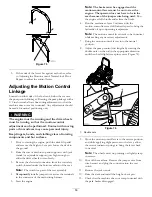
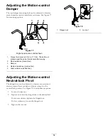
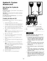
background image

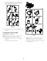
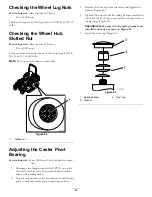
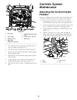
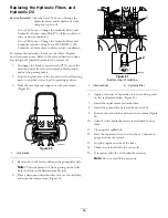
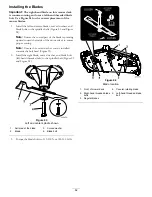
Figure 69

1.

Idler spring

4.

Idler pulley

2.

Counter-rotating belt

5.

Square hole for ratchet

3.

Double pulley

7.

Use a ratchet in the square hole in the idler arm to
remove tension on the idler spring (Figure 69).

8.

Remove the belt from the mower deck pulley.

9.

Remove the belt from the remaining pulleys.

10.

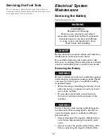
Using the ratchet in the square hole, install the new
belt around the mower pulleys and the idler pulleys
(Figure 71).

11.

Lower the floor pan and install the bolt to hold the
floor pan down.

Replacing the Mower Deck
Belt

Squealing when the belt is rotating, blades slipping when
cutting grass, frayed belt edges, burn marks and cracks are
signs of a worn mower belt. Replace the belt if any of these
conditions are evident.

Important:

The fasteners on the covers of this machine

are designed to remain on the cover after removal.
Loosen all of the fasteners on each cover a few turns so
that the cover is loose but still attached, then go back
and loosen them until the cover comes free. This will
prevent you from accidentally stripping the bolts free
of the retainers.

1.

Disengage the PTO, move the motion control levers to
the neutral locked position and set the parking brake.

2.

Stop the engine, remove the key, and wait for all moving
parts to stop before leaving the operating position.

3.

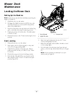
Lower the mower to the 76 mm (3 inches) height of cut.

4.

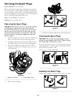
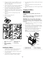
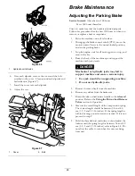
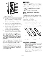
Remove the belt covers (Figure 70).

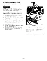
g024666

Figure 70

Left side shown

1.

Push tab down

2.

Remove belt cover

5.

Remove the counter-rotating belt; refer to Replacing
the Counter-Rotating Belt 
(page 49).

6.

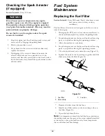
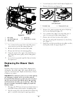
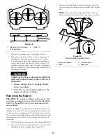
Use a ratchet in the square hole in the idler arm to
remove tension on the idler spring (Figure 71).

7.

Remove the belt from the mower deck pulley.

8.

Lift up on the belt-guide tab and remove the existing
belt (Figure 71).

9.

Install the new belt around the mower pulleys and the
clutch pulley under the engine (Figure 71).

50

Содержание 74942TE

Страница 1: ... 849 Rev A Z Master Professional 6000 Series Riding Mower with 152cm TURBO FORCE Rear Discharge Mower Model No 74942TE Serial No 314000001 and Up g024514 Register at www Toro com Original Instructions EN 3380 849 A ...

Страница 2: ...commercial properties It is not designed for cutting brush or for agricultural uses Read this information carefully to learn how to operate and maintain your product properly and to avoid injury and product damage You are responsible for operating the product properly and safely You may contact Toro directly at www Toro com for product and accessory information help finding a dealer or to register...

Страница 3: ...k Plugs 39 Checking the Spark Arrester if equipped 40 Fuel System Maintenance 40 Replacing the Fuel Filter 40 Servicing the Fuel Tank 41 Electrical System Maintenance 41 Servicing the Battery 41 Servicing the Fuses 43 Jump Starting the Machine 43 Drive System Maintenance 44 Checking the Seat Belt 44 Checking the Rollover Protection System ROPS Knobs 44 Adjusting the Tracking 45 Checking the Tire P...

Страница 4: ...e the equipment is to be used and remove all objects which may be thrown by the machine Replace worn or damaged silencers Before using always visually inspect to see that the blades blade bolts and cutter assembly are not worn or damaged Replace worn or damaged blades and bolts in sets to preserve balance On multi bladed machines take care as rotating one blade can cause other blades to rotate Ope...

Страница 5: ...rty damage use extreme care in handling gasoline Gasoline is extremely flammable and the vapors are explosive Extinguish all cigarettes cigars pipes and other sources of ignition Use only an approved fuel container Never remove fuel cap or add fuel with the engine running Allow engine to cool before refueling Never refuel the machine indoors Never store the machine or fuel container where there is...

Страница 6: ... approved attachments The warranty may be voided if you use unapproved attachments Slope Operation Do not mow slopes greater than 15 degrees Do not mow near drop offs ditches steep banks or water Wheels dropping over edges can cause rollovers which may result in serious injury death or drowning Do not mow slopes when grass is wet Slippery conditions reduce traction and could cause sliding and loss...

Страница 7: ...n Uncertainty Value K of 1 dBA The sound power level was determined according to the procedures outlined in ISO 11094 Vibration Level Hand Arm Measured vibration level for right hand 1 1 m s2 Measured vibration level for left hand 3 9 m s2 Uncertainty Value K 2 0 m s2 Measured values were determined according to the procedures outlined in EN 836 Whole Body Measured vibration level 0 33 m s2 Uncert...

Страница 8: ... degrees Use the slope chart to determine the degree of slope of hills before operating Do not operate this machine on a slope greater than 15 degrees Fold along the appropriate line to match the recommended slope 2 Align this edge with a vertical surface a tree building fence pole etc 3 Example of how to compare slope with folded edge 8 ...

Страница 9: ...w 106 2655 1 Warning do not touch or approach moving belts remove the ignition key and read the instructions before servicing or performing maintenance 106 5517 1 Warning do not touch the hot surface 107 3069 1 Warning there is no rollover protection when the roll bar is down 2 To avoid injury or death from a rollover accident keep the roll bar in the fully raised and locked position and wear the ...

Страница 10: ...parts keep all guards in place 114 4466 1 Main 25A 3 Charge 25A 2 PTO 10A 4 Auxiliary 15A 114 4470 1 Read the Operator s Manual 3 Locked 2 Height of cut 4 Unlocked 116 1716 1 Fuel 6 Hour meter 2 Empty 7 PTO 3 Half 8 Parking brake 4 Full 9 Neutral 5 Battery 10 Operator presence switch 116 5988 1 Parking brake engaged 2 Parking brake disengaged 10 ...

Страница 11: ...erate the without deflector discharge cover or grass collection system in place 3 Cutting dismemberment of hand or foot stay away from moving parts keep all guards and shields in place 117 3863 1 Wheel lug nut torque 90 95 ft lb 122 129 N m 2 Wheel hub slotted nut 211 260 ft lb 286 352 N m 3 Read the Operator s Manual before performing any maintenance check torque after first 100 hours and then ev...

Страница 12: ...ting machine do not use ramps with inclination greater than 10 degrees 120 5897 1 Choke 4 Slow 2 Fast 5 Power take off PTO Blade control switch 3 Continuous variable setting 125 9384 1 Read the Operator s Manual for information on lubricating the idler pulley pivots 3 Counter clockwise rotation 2 Lubricate the spindles every 50 operating hours 4 Clockwise rotation 127 6651 1 Read the Operator s Ma...

Страница 13: ...ou are trained 6 Crushing dismemberment hazard of bystanders do not carry passengers look forward and down when operating the machine look behind and down when reversing 3 Warning engage the parking brake stop the engine and remove the ignition key read the instructions before servicing or performing maintenance 7 Cutting dismemberment hazard hand or foot stay away from moving parts and keep all g...

Страница 14: ...s Some or all of these symbols are on your battery 1 Explosion hazard 5 Read the Operator s Manual 9 Flush eyes immediately with water and get medical help fast 2 No fire open flames or smoking 6 Keep bystanders a safe distance from the battery 10 Contains lead do not discard 3 Caustic liquid chemical burn hazard 7 Wear eye protection explosive gases can cause blindness and other injuries 4 Wear e...

Страница 15: ...the bars light up when the ignition switch is on Figure 6 The indicator light appears when the fuel level is low approximately 3 8 L 1 US gallon remaining in the fuel tank Figure 6 1 Fuel gauge bars 4 Safety interlock symbols 2 Battery light 5 Low fuel indicator light 3 Hour meter Safety interlock Indicators There are symbols on the hour meter and the indicate with a black triangle that the interl...

Страница 16: ...ition Fuel shutoff Valve Close the fuel shutoff valve under the seat when transporting or storing the machine Attachments Accessories A selection of Toro approved attachments and accessories is available for use with the machine to enhance and expand its capabilities Contact your Authorized Service Dealer or Distributor or go to www Toro com for a list of all approved attachments and accessories S...

Страница 17: ...not operate without entire exhaust system in place and in proper working condition DANGER In certain conditions during fueling static electricity can be released causing a spark which can ignite the gasoline vapors A fire or explosion from gasoline can burn you and others and can damage property Always place gasoline containers on the ground away from your vehicle before filling Do not fill gasoli...

Страница 18: ...d 1 Park the machine on level ground 2 Shut the engine off and set the parking brake 3 Clean around the fuel tank cap 4 Fill the fuel tank to the bottom of the filler neck Ensure there is empty space in the tank to allow the gasoline to expand Figure 7 g024209 G012429 1 2 4 3 5 Figure 7 Checking the Engine oil Level Before you start the engine and use the machine check the oil level in the engine ...

Страница 19: ...cts and do not contact them Important Lower the roll bar only when absolutely necessary Important Ensure that the seat is secured to the machine 1 To lower the roll bar apply forward pressure to the upper part of the roll bar 2 Pull both knobs out and rotate them 90 so they are not engaged Figure 8 3 Lower the roll bar to the down position Figure 8 Figure 8 1 ROPS knob 3 Roll bar in the upright po...

Страница 20: ...less than 15 degrees or flat areas 3 Water 2 Danger Zone use a walk behind mower and or a hand trimmer on slopes greater than 15 degrees near drop offs and water CAUTION This machine produces sound levels in excess of 85 dBA at the operators ear and can cause hearing loss through extended periods of exposure Wear hearing protection when operating this machine The use of protective equipment for ey...

Страница 21: ...e control Switch PTO G009174 Figure 14 Operating the Throttle The throttle control can be moved between Fast and Slow positions Figure 15 Always use the fast position when turning on the mower deck with the blade control switch PTO G008946 Figure 15 Operating the Choke Use the choke to start a cold engine 1 If the engine is cold use the choke to start the engine 2 Pull up on the choke knob to enga...

Страница 22: ... can burn out the starter motor Note Additional starting cycles may be required when starting the engine for the first time after the fuel system has been without fuel completely STA RT RU N STO P G008947 Figure 17 2 Turn the ignition key to stop to stop the engine Using the Fuel shutoff Valve The fuel shutoff valve is located under the seat Move the seat forward to access it Close the fuel shutof...

Страница 23: ... than 5 seconds at a time If the engine fails to start allow a 15 second cool down period between attempts Failure to follow these instructions can burn out the starter motor Note Additional starting cycles may be required when starting the engine for the first time after the fuel system has been without fuel completely STA RT RU N STO P G008947 Figure 20 1 Off 3 Start 2 Run Stopping the Engine CA...

Страница 24: ...en the component is in the correct position a triangle will light up in the corresponding square G009181 1 Figure 22 1 Triangles light up when the interlock components are in the correct position Testing the Safety interlock System Service Interval Before each use or daily Test the safety interlock system before you use the machine each time If the safety system does not operate as described below...

Страница 25: ...ontrol of the machine and injure someone or damage the machine Use caution when making turns Slow the machine down before making sharp turns Using the Motion control Levers Figure 23 1 Motion control lever neutral lock position 4 Backward 2 Center unlocked position 5 Front of the machine 3 Forward Driving Forward Note The engine will stop if the motion control levers are moved with the parking bra...

Страница 26: ...ove or attempt to operate the tractor while it is unattended Always remove the ignition key and set the parking brake when leaving the machine unattended even if just for a few minutes Adjusting the Height of Cut Using the Transport Lock The transport lock has two positions and is used with the deck lift pedal There is a lock position and a unlock position for the transport position The transport ...

Страница 27: ... change the height of cut it is recommended to adjust the height of the anti scalp rollers 1 Disengage the blade control switch PTO move the motion control levers to the neutral locked position and set the parking brake 2 Stop the engine remove the key and wait for all moving parts to stop before leaving the operating position 3 Adjust the anti scalp rollers as shown in Figure 28 and Figure 29 to ...

Страница 28: ... provide a smooth and comfortable ride Position the seat where you are most comfortable To adjust it turn the knob in front either direction to provide the best comfort Figure 32 g019768 1 Figure 32 1 Seat suspension knob Using the Drive wheel Release Valves WARNING Hands may become entangled in the rotating drive components below the engine deck which could result in serious injury Stop the engin...

Страница 29: ...tions Knowing this information could help you your family pets or bystanders avoid injury WARNING Driving on the street or roadway without turn signals lights reflective markings or a slow moving vehicle emblem is dangerous and can lead to accidents causing personal injury Do not drive machine on a public street or roadway To transport the machine 1 If using a trailer connect it to the towing vehi...

Страница 30: ...g the seat belt when loading the machine Ensure that the ROPS will clear the top of an enclosed trailer Use only a single full width ramp do not use individual ramps for each side of the machine If individual ramps must be used use enough ramps to create an unbroken ramp surface wider than the machine Do not exceed a 15 degree angle between the ramp and the ground or between the ramp and the trail...

Страница 31: ...tting height higher than usual and cut the grass at this setting Then cut the grass again using the lower normal setting Stopping If the you must stop the forward motion of the machine while mowing a clump of grass clippings may drop onto the lawn To avoid this move onto a previously cut area with the blades engaged Keeping the Underside of the Mower Clean Clean clippings and dirt from the undersi...

Страница 32: ...d gap the spark plugs Check and clean engine cooling fins and shrouds Every 200 hours Change the engine oil filter Every 250 hours Replace the primary air filter Check the secondary air filter Change the hydraulic filters and hydraulic oil when using Mobil 1 oil more often in dirty or dusty conditions Every 500 hours Replace the secondary air filter Replace the fuel filter more often in dirty or d...

Страница 33: ...o the fittings until grease begins to ooze out of the bearings 5 Wipe up any excess grease Where to Add Light Oil or Spray Lubrication Service Interval Every 100 hours Lubricate the deck lift pivots G017050 Figure 36 Where to Grease the Mower Service Interval Every 50 hours Grease the mower deck spindles Yearly Grease the pump belt idler arm Yearly Grease the front caster pivots more often in dirt...

Страница 34: ...ge the parking brake Figure 41 1 Seal guard 2 Spacer nut with wrench flats 2 Raise the front of the machine up and support it with jack stands or equivalent support just high enough to allow the front wheels to turn freely 3 Remove the caster wheel from the caster forks 4 Remove the seal guards from the wheel hub 5 Remove one of the spacer nuts from the axle assembly in the caster wheel Note that ...

Страница 35: ...e on spacer nut until there is a slight amount of drag Apply thread locking adhesive Engine Maintenance WARNING Contact with hot surfaces may cause personal injury Keep hands feet face clothing and other body parts away the muffler and other hot surfaces Servicing the Air Cleaner Service Interval Every 250 hours Replace the primary air filter Every 250 hours Check the secondary air filter Every 50...

Страница 36: ...it Important Do not press on the soft inside area of the filter 4 Install the air cleaner cover with the breather cap down and rotate so the retaining clamps lock the cover in place Figure 42 Servicing the Engine Oil Oil Type Detergent oil API service SG SH SJ or SL Oil Capacity With a filter change 2 3 L 77 8 ounces without a filter change 2 1 L 71 0 ounces Viscosity See the table below Figure 43...

Страница 37: ... let it run for 5 minutes This warms the oil so it drains better 2 Park the machine so that the rear is slightly lower than the front to ensure that the oil drains completely 3 Disengage the PTO move the motion control levers to the neutral locked position and set the parking brake 4 Stop the engine remove the key and wait for all moving parts to stop before leaving the operating position Figure 4...

Страница 38: ...Filter Service Interval Every 200 hours Note Change the engine oil filter more frequently when operating conditions are extremely dusty or sandy 1 Drain the oil from the engine refer to Changing the Engine Oil 2 Change the engine oil filter Figure 47 g024213 G008748 3 4 1 2 3 4 5 6 Figure 47 Note Ensure that the oil filter gasket touches the engine and then an extra 3 4 turn is completed 3 Fill th...

Страница 39: ...top the engine remove the key and wait for all moving parts to stop before leaving the operating position 2 Disengage the PTO move the motion control levers to the neutral locked position and set the parking brake 3 Remove the hydraulic unit shroud and the 2 bolts attached to it Figure 48 This gives you access to the front spark plug G012432 2 1 2 Figure 48 1 Hydraulic unit shroud 2 Loosen these 2...

Страница 40: ...ly whichever comes first more often in dirty or dusty conditions The fuel filter is located near the engine on the front or rear side of the engine 1 Disengage the PTO move the motion control levers to the neutral locked position and set the parking brake 2 Stop the engine remove the key and wait for all moving parts to stop before leaving the operating position 3 Allow the machine to cool down 4 ...

Страница 41: ...ing Wear safety glasses to shield your eyes and rubber gloves to protect your hands Removing the Battery WARNING Battery terminals or metal tools could short against metal machine components causing sparks Sparks can cause the battery gases to explode resulting in personal injury When removing or installing the battery do not allow the battery terminals to touch any metal parts of the machine Do n...

Страница 42: ...minal 3 Then install the negative black battery cable and ground wire to the negative battery terminal 4 Secure the cables with 2 bolts 2 washers and 2 locknuts Figure 53 5 Slide the red terminal boot onto the positive red battery post 6 Install the clamp and secure it with the wing nut Figure 53 Charging the Battery WARNING Charging the battery produces gases that can explode Never smoke near the...

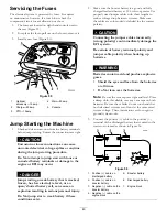
Страница 43: ...e the booster battery is a good and fully charged lead acid battery at 12 6 volts or greater Use properly sized jumper cables with short lengths to reduce voltage drop between systems Make sure the cables are color coded or labeled for the correct polarity CAUTION Connecting the jumper cables incorrectly wrong polarity can immediately damage the EFI system Be certain of battery terminal polarity a...

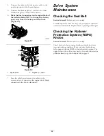
Страница 44: ...rder of connection the engine block black connection is the first to disconnect Drive System Maintenance Checking the Seat Belt Service Interval Before each use or daily Visually inspect seat belt for wear cuts and proper operation of retractor and buckle Replace before operating if damaged Checking the Rollover Protection System ROPS Knobs Service Interval Before each use or daily Check that both...

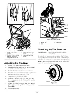
Страница 45: ...tracks to the right loosen the bolts and adjust the left stop plate on the left T slot until the machine tracks straight 7 If it tracks to the left loosen the bolts and adjust the right stop plate on the right T slot until the machine tracks straight 8 Tighten the stop plate g024605 Figure 60 Left control lever shown 1 Control lever 3 Stop plate 2 Bolt Checking the Tire Pressure Service Interval E...

Страница 46: ...500 hours Yearly whichever comes first 1 Disengage the blade control switch PTO move the motion control levers to the neutral locked position and set the parking brake 2 Stop the engine remove the key and wait for all moving parts to stop before leaving the operating position 3 Remove the dust cap from the caster and tighten the locknut Figure 63 4 Tighten the locknut until the spring washers are ...

Страница 47: ... the air intake screen recoil starter and fan housing Figure 65 4 Clean the debris and grass from the engine parts 5 Install air intake screen recoil starter and fan housing Figure 65 Figure 65 1 Engine guard 4 Fan housing 2 Engine air intake screen 5 Screw 3 Bolt Checking and Cleaning the Hydraulic unit Shrouds Service Interval Before each use or daily Important The fasteners on the covers of thi...

Страница 48: ...parts to stop and remove the key 4 Raise the back of the machine up and support the machine with jack stands DANGER Mechanical or hydraulic jacks may fail to support machine and cause a serious injury Use jack stand when supporting machine Do not use hydraulic jacks 5 Remove the rear wheels from the machine 6 Remove any debris from the brake area 7 Rotate the drive wheel release handle to the rele...

Страница 49: ...r squealing when the belt is rotating blades slipping when cutting grass frayed belt edges burn marks and cracks are signs of a worn mower belt Replace the mower belt if any of these conditions are evident Replacing the Counter Rotating Belt Squealing when the belt is rotating blades slipping when cutting grass frayed belt edges burn marks and cracks are signs of a worn mower belt Replace the belt...

Страница 50: ... Loosen all of the fasteners on each cover a few turns so that the cover is loose but still attached then go back and loosen them until the cover comes free This will prevent you from accidentally stripping the bolts free of the retainers 1 Disengage the PTO move the motion control levers to the neutral locked position and set the parking brake 2 Stop the engine remove the key and wait for all mov...

Страница 51: ...igure 71 Make sure the spring ends are seated in the anchor grooves 12 Install the belt covers Figure 72 g024667 Figure 72 1 Position the belt cover 3 Ensure the tab is under the metal catch 2 Slide belt cover under the side catches Replacing the Hydraulic pump Drive Belt 1 Disengage the PTO and set the parking brake 2 Stop the engine remove the key and wait for all moving parts to stop before lea...

Страница 52: ...gure 73 10 Install the mower belt Refer to Replacing the Mower Belt Controls System Maintenance Adjusting the Control Handle Position There are 2 height positions for the control levers high and low Remove the bolts to adjust the height for the operator 1 Disengage the PTO move the motion control levers to the neutral locked position and set the parking brake 2 Stop the engine remove the key and w...

Страница 53: ...4 Temporarily install a jumper wire across the terminals in the connector of the main wiring harness 5 Start the engine Note The brake must be engaged and the motion control levers must be out to start the engine The operator does not have to be in the seat because of the jumper wire being used Run the engine at full throttle and release the brake 6 Run the machine at least 5 minutes with the moti...

Страница 54: ...stance firmest feel 3 Damper 4 Medium resistance medium feel 5 Least resistance softest feel Adjusting the Motion control Neutral lock Pivot The flanged nut can be adjusted to obtain a more desired motion control lever resistance when moving it to the neutral lock position See Figure 78 for adjustment options 1 Loosen the jam nut 2 Tighten or loosen the flanged nut to the desired feel For more res...

Страница 55: ...rvoir 9 Remove the dipstick and look at the end Figure 79 Note If the oil level is at the add mark slowly pour only enough oil into the hydraulic reservoir to raise the level to the full or H line Important Do not overfill the hydraulic units with oil as damage may occur Do not run the machine with the oil below the add mark 10 Install the dipstick 11 Repeat procedure for the opposite dipstick G01...

Страница 56: ...he operating position 3 Raise the machine and support it with jack stands Figure 80 Figure 80 1 Jack stands 4 Remove both the mower belt and the pump drive belt Note This will prevent oil from getting on the belts Refer to Belts in the Maintenance Section 5 Place a drain pan under the filter remove the old filter and wipe the surface clean Figure 81 G008968 1 2 Figure 81 Bottom view of machine 1 F...

Страница 57: ...rface 2 Stop engine wait for all moving parts to stop and remove key Engage parking brake 3 Check the tire pressure in the drive tires Proper inflation pressure for tires is 90 kPa 13 psi Adjust if necessary 4 Position the transport lock in the latching position 5 Push the deck lift pedal all the way forward and the deck will latch at the 14 cm 5 1 2 inches transport position Figure 82 1 3 2 G0170...

Страница 58: ...adjustment to achieve accurate cut height the single point adjustment can be utilized to gain more adjustment 11 To adjust the single point system loosen the two bolts at the bottom of the height of cut plate Refer to Figure 85 1 g017029 Figure 85 1 Bolts at the bottom of the height of cut plate 12 If the deck is too low tighten the single point adjustment bolt by rotating it clockwise If the deck...

Страница 59: ...s damaged or worn replace it immediately with a genuine Toro replacement blade For convenient sharpening and replacement you may want to keep extra blades on hand DANGER A worn or damaged blade can break and a piece of the blade could be thrown into the operator s or bystander s area resulting in serious personal injury or death Inspect the blade periodically for wear or damage Replace a worn or d...

Страница 60: ...ght hand blade on this mower deck is counter rotating and uses a left hand threaded blade bolt Use Figure 90 for the correct placement of the mower blades Replace the blades if a solid object is hit if the blade is out of balance or is bent To ensure optimum performance and continued safety conformance of the machine use genuine Toro replacement blades Replacement blades made by other manufacturer...

Страница 61: ... cutting edge at both ends of the blade Figure 91 Maintain the original angle The blade retains its balance if the same amount of material is removed from both cutting edges Figure 91 1 Sharpen at original angle 2 Check the balance of the blade by putting it on a blade balancer Figure 92 If the blade stays in a horizontal position the blade is balanced and can be used If the blade is not balanced ...

Страница 62: ...rd the inside of the mower deck to ensure proper cutting Note Ensure the curved washer cone is installed towards the bolt head Figure 93 2 Install the right blade curved washer and blade bolt left hand threaded bolt to the spindle shaft Figure 93 and Figure 94 Figure 93 Left and center spindle shown 1 Sail area of the blade 3 Curved washer 2 Blade 4 Blade bolt 3 Torque the blade bolts to 115 150 N...

Страница 63: ...pin in the 7 6 cm 3 inch cutting height location This locks the deck lift arms in the lowest position when the deck is removed and the stored energy in the deck spring is released 4 Remove the belt covers 5 Lift up the floor pan and insert a ratchet into the square hole in the deck idler Figure 95 6 Rotate the mower deck idler clockwise lift up on the belt guide tab and remove the mower deck belt ...

Страница 64: ...ing under the Mower Service Interval Before each use or daily 1 Disengage the blade control switch PTO move the motion control levers to the neutral locked position and set the parking brake 2 Stop the engine remove the key and wait for all moving parts to stop before leaving the operating position 3 Raise the mower to the transport position Disposing of Waste Engine oil batteries hydraulic oil an...

Страница 65: ...dirt from the underside of the mower then wash the mower with a garden hose Note Run the machine with the blade control switch PTO engaged and the engine at high idle for 2 to 5 minutes after washing 11 Check the condition of the blades refer to Servicing the Cutting Blades in the Maintenance Section 12 For storage over 30 days prepare the machine as follows A Add a petroleum based stabilizer cond...

Страница 66: ... or damaged 9 Check the electrical connections for good contact Clean the connector terminals thoroughly with electrical contact cleaner apply dielectric grease and make the appropriate connections 10 The relay or switch is worn or damaged 10 Contact an Authorized Service Dealer 11 The spark plug is fouled or improperly gapped 11 Adjust or replace the spark plug The engine does not start starts ha...

Страница 67: ... level 3 Level the mower deck from side to side and front to rear 4 The underside of mower is dirty 4 Clean the underside of the mower 5 The tire pressure is not correct 5 Adjust the tire pressure The machine produces an uneven cutting height 6 The blade spindle is bent 6 Contact an Authorized Service Dealer 1 The mower deck belt is worn loose or broken 1 Install a new deck belt 2 The mower deck b...

Страница 68: ...Schematics Wire Diagram Rev A 68 ...

Страница 69: ...Notes 69 ...

Страница 70: ...Notes 70 ...

Страница 71: ... 3766 3636 Jean Heybroek b v Netherlands 31 30 639 4611 Victus Emak Poland 48 61 823 8369 European Privacy Notice The Information Toro Collects Toro Warranty Company Toro respects your privacy In order to process your warranty claim and contact you in the event of a product recall we ask you to share certain personal information with us either directly or through your local Toro company or dealer ...

Страница 72: ...or Obtaining Warranty Service If you think that your Toro Product contains a defect in materials or workmanship follow this procedure 1 Contact your seller to arrange service of the product If for any reason it is impossible for you to contact your seller you may contact any Toro Authorized Distributor to arrange service 2 Bring the product and your proof of purchase sales receipt to the Service D...

Отзывы: