4
g024245
3
2
1
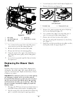
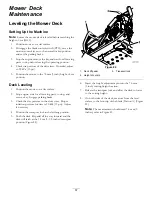
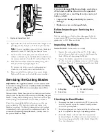
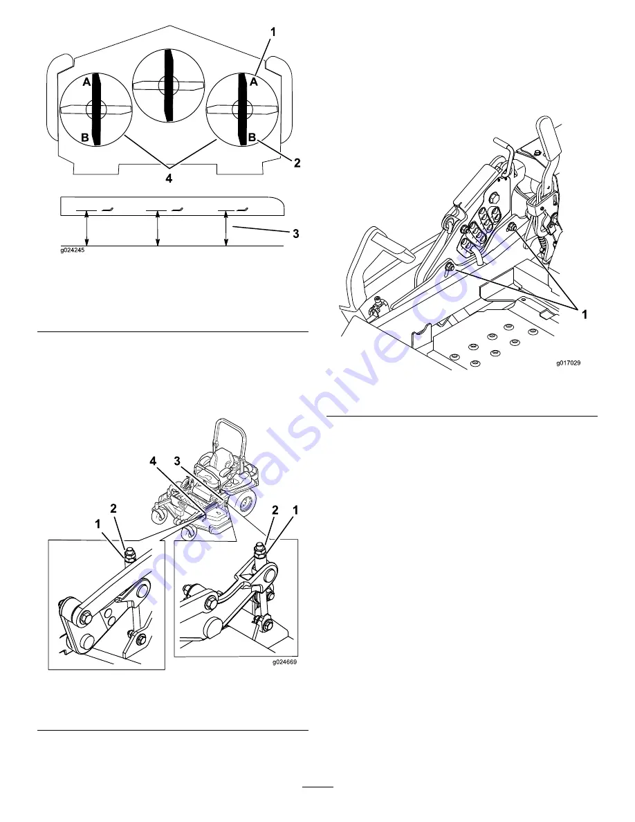
Figure 83
1.
76 mm (3 inches) at A is
correct
3.
Measure here from the
blade tip to hard surface
2.
8.3 cm (3-1/4 inches) at B
is correct
4.
Measure at A and B on
both sides
9.
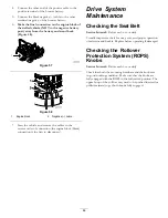
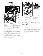
If needed, fine-tune the adjustment nut on the front
deck adjustment by turning it (see Figure 84).
Note:
To increase the height, turn the adjustment
nut clockwise; to decrease the height, turn the nut
counterclockwise.
g024669
1
2
2 1
4 3
Figure 84
1.
Adjustment nut
3.
Rear deck adjustment
2.
Jam nut
4.
Front deck adjustment
10.
If the front deck links do not have enough adjustment
to achieve accurate cut height , the single point
adjustment can be utilized to gain more adjustment.
11.
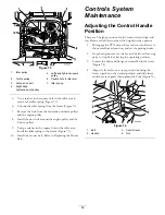
To adjust the single point system, loosen the two bolts
at the bottom of the height-of-cut plate. Refer to
Figure 85.
1
g017029
Figure 85
1.
Bolts at the bottom of the height-of-cut plate
12.
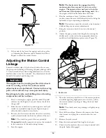
If the deck is too low, tighten the single point
adjustment bolt by rotating it clockwise. If the deck is
too high, loosen the single point adjustment bolt by
rotating it counterclockwise (Figure 86).
Note:
Loosen or tighten the single point adjustment
bolt enough to move the height-of-cut plate mounting
bolts at least 1/3 the length of the available travel
in their slots. This will regain some up and down
adjustment on each of the four deck links.
58
Содержание 74942TE
Страница 68: ...Schematics Wire Diagram Rev A 68 ...
Страница 69: ...Notes 69 ...
Страница 70: ...Notes 70 ...

