background image

26

6.

Adjust the left–hand side. It is very important that the

left side and right side are adjusted equally (from the

frame). Do not use the floor to adjust the

perpendicularity of the reel shaft to the sweeper frame.

7.

Verify that there is no interference when the PTO

engagement handle is in OFF position.

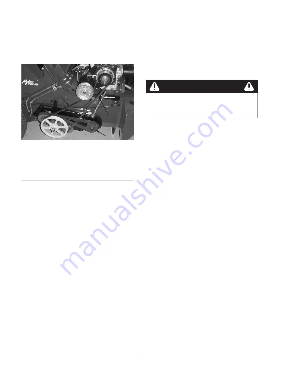
1

2

3

4

5

6

7

8

Figure 25

1. Reel height adjusting nut

(right hand side)

2. Upper idler
3. Idler adjusting arm
4. Front reel pulley

5. Clutch switch adjustment
6. Electric clutch/brake
7. Upper drive belt
8. Clutch switch flag

Belt Removal/Installation

1.

Position machine on a level surface, shut the engine off,

set the parking brake and remove the key from the

ignition switch.

2.

Remove belt guards.

3.

The upper or lower belt can be removed or installed

without removing both belts.

4.

To remove the upper belt, loosen the upper idler

(Fig. 25) and remove belt from machine.

5.

To install upper belt, first verity that the upper idler

(Fig. 25) is loosened and slides freely. Install belt on

machine. To tighten idler, push down on idler with

approximately 30 lbs. of force and tighten idler bolt. Do

not use a lever for mechanical advantage. 

Do not over

tension belt. An over–tensioned belt can cause

premature failure or wear. The electric clutch and

other reel drive components are subject to damage

when belts are over–tensioned.

6.

To remove lower reversing belt, loosen the two bolts on

the rear idler adjustment arm (Fig. 25). Move

adjustment arm forward and remove belt.

7.

To install lower reversing belt, push idler adjustment

arm forward. Install reversing belt.

Note:

 The inside and outside of the belt are not the same.

When looking at the front reel pulley (Fig. 25), with the

belt installed, there should be two wide grooves on either

side visible. Tighten the idler adjustment arm by pulling

rearward with approximately 30 lbs. Torque both clamping

bolts to 48 ft–lbs. Do not use a lever or a pry–bar for

mechanical advantage when tensioning the belt with the

idler adjustment arm.

8.

Re–tension new belts after l0 hours of operation.

An incorrectly adjusted reel switch may cause
unintended engagement of the reels and could
cause injury.

Caution

Clutch Switch Adjustment

The clutch switch should never need adjusting. If the clutch

fails to engage or disengage according to the position of the

Reel PTO Engagement Handle, adjust the clutch switch.

1.

Position machine on a level surface, shut the engine off,

set parking brake and remove the key from the ignition

switch.

2.

Inspect the complete reel lift system including the reel

engagement handle. Look for any worn or bent

components that may cause the engagement switch to

be out of adjustment.

3.

Replace or repair any damaged components.

If all reel lift system components are in proper condition,

adjust the reel switch bracket.

1.

Place the PTO engagement handle in the OFF position.

2.

Loosen the three bolts on the clutch switch bracket

(Fig. 25).

3.

Slide the clutch switch bracket until there is 1/8” of the

clutch switch flag (Fig. 25) protruding through the

bottom of the clutch switch bracket.

4.

Tighten the three bolts and reassemble in reverse order.

Electric Brake Clutch

Adjustment

Every 200 hours check for proper air gap on the electric

clutch brake. Failure to maintain the correct air gap could

result in clutch not engaging even though it is electrically

energized.

1.

Position machine on a level surface, shut the engine off,

set the parking brake and remove the key from the

ignition switch.

Содержание 44044

Страница 1: ...Operator s Manual English EN Form No 3350 447 Rev A Turf Sweeper 4800 Model No 44044 Serial No 240000001 and Up...

Страница 2: ...rication 20 Lubricate Fittings and Bearings 20 Maintenance 21 Changing Engine Oil and Filter 21 General Precleaner and Air Cleaner Maintenance 22 Clean and Lubricate Foam Precleaner 22 Service Air Cle...

Страница 3: ...machine Improper use or maintenance of the machine can result in injury or death To reduce the potential for injury or death comply with the following safety instructions Supervisor s Responsibilitie...

Страница 4: ...r should keep both hands on steering wheel whenever possible DON T TAKE AN INJURY RISK When a person or pet appears unexpectedly in or near the sweeping area STOP SWEEPING Careless operation combined...

Страница 5: ...damage Keep body and hands away from pin hole leaks or nozzles that eject high pressure hydraulic fluid Use cardboard or paper to find hydraulic leaks Fluid accidentally injected into the skin must b...

Страница 6: ...wheel ALWAYS ensure that the wheel motor axle nut is torqued to 200 400 ft lb To be sure of optimum performance and safety always purchase genuine TORO replacement parts and accessories Replacement pa...

Страница 7: ...afety decals and instructions are easily visible to the operator and are located near any area of potential danger Replace any decal that is damaged or lost 87 6020 53 4420 27 7310 85 7490 98 8880 80...

Страница 8: ...8 01 506 0090 95 0370 1 Fast 2 Continuous variable setting 3 Slow 95 0371 1 Choke on 2 Choke off 95 0383 95 0389 95 0384 95 0387 95 0388 88 8950...

Страница 9: ...st Controls Throttle choke Reel PTO Engagement handle parking brake hopper release handle and ignition switch are all hand operated Forward reverse traction pedal is foot operated Gauges Hour meter hy...

Страница 10: ...n greatly enhances the filling capacity of the hopper You may find that the particular debris that you are sweeping tends to fall back into the hopper inlet and clogs the reels When this occurs remova...

Страница 11: ...CAUSE PROPERTY DAMAGE Caution must be used when storing or handling gasoline Do not fill fuel tank while engine is running or hot or when machine is in an enclosed area Vapors may build up and be ign...

Страница 12: ...with controlled low temperature flow properties and anti wear protection The reservoir is filled at the factory with approximately 28 quarts of Mobil DTE 13M hydraulic fluid Hydraulic oil viscosity w...

Страница 13: ...ne screen 200 mesh and ensure funnel and oil are clean This procedure prevents accidental contamination of the hydraulic oil which will damage the hydraulic system 1 Figure 3 1 Dipstick cap Check Torq...

Страница 14: ...use is blown the engine will not crank Hour Meter Fig 5 Indicates total hours of machine operation The hour meter starts to function whenever the key switch is rotated to the ON position Reel PTO Enga...

Страница 15: ...foot operated and is used to make the machine move forward and backward and to stop the machine Using the heel and toe of the right foot depress top of pedal to move forward and bottom of pedal to mov...

Страница 16: ...shut off the parking brake must be engaged to prevent accidental movement of the machine Caution Hopper Door Release Handle Fig 9 The hopper is dumped manually with the hopper door release handle 1 Fi...

Страница 17: ...position or the Reel PTO Engagement handle is in the HIGH or LOW engaged position B A disconnected or malfunctioning safety interlock switch could allow the engine to continue running when the Reel PT...

Страница 18: ...nition key OFF to stop engine Pushing or Towing Sweeper In case of an emergency the sweeper can be pushed or towed for a short distance However TORO does not recommend this as standard procedure Impor...

Страница 19: ...ing the Hopper Danger TIP OVER ELECTRICAL SHOCK COULD CAUSE SERIOUS INJURY OR DEATH NEVER dump hopper on a slope Always dump hopper on level ground Dump only in area clear of overhead wires and other...

Страница 20: ...ust be lubricated daily when operating conditions are extremely dusty and dirty Dusty and dirty operating conditions could cause dirt to got into the bearings and bushings resulting in accelerated wea...

Страница 21: ...k Be sure to allow ample time for complete drainage 4 Reinstall drain plug 5 Remove the old filter Wipe off surface where oil filter mounts Allow oil filter to drain 6 Apply a thin coating of new oil...

Страница 22: ...r cover 2 1 Figure 20 1 Air cleaner cover 2 Air cleaner cover knob 3 Remove precleaner from paper element 4 Wash precleaner in warm water with detergent Rinse precleaner thoroughly until all traces of...

Страница 23: ...e plug and fall into the cylinder The result is usually a damaged engine 1 Turn engine off set parking brake and remove key from ignition switch 2 Before removing spark plug clean the area around the...

Страница 24: ...Important Do not continue to operate machine if hydraulic vacuum gauge remains in the red zone after hydraulic oil has reached stable operating temperature Continuing to operate machine with gauge in...

Страница 25: ...ace fuel filter after 100 hours of operation 1 Place a drain pan under filter 2 Clamp both fuel lines that connect to fuel filter so gasoline cannot drain when lines are removed 1 Figure 24 1 Fuel fil...

Страница 26: ...ing at the front reel pulley Fig 25 with the belt installed there should be two wide grooves on either side visible Tighten the idler adjustment arm by pulling rearward with approximately 30 lbs Torqu...

Страница 27: ...to actuate lever 3 Tighten set screw after adjustment has been made Adjusting Traction Pedal If the machine moves in either direction when traction pedal is in the neutral position the traction cam mu...

Страница 28: ...s To install new reel fingers 1 Place the reel finger in the slot and pull as far as possible 2 Place the end of the puller on the finger 3 Push down on puller to install finger Figure 29 Note The pul...

Страница 29: ...rning 1 Battery electrolyte level must be properly maintained and the top of the battery kept clean If the machine is stored in a location on where temperatures are extremely high the battery will run...

Страница 30: ...r reel deflector above front reel 1 Replace missing or broken fingers 2 Replace belt adjust tension 3 Replace key 4 Adjust height See Sweeper Reel Height Adjustment 5 Bend hopper floor back to seal ho...

Страница 31: ...31 Hydraulic Schematic...

Страница 32: ...32 Electrical Schematic...

Страница 33: ...icate gate pivots Lubricate all grease fittings Check battery cable connections Change engine oil and filter Every 100 hours Replace air filter Clean air intake cooling areas Check reel fingers Replac...

Страница 34: ...noises Check for unusual operating noises Check tire pressure Check hydraulic hoses for damage Check for fluid leaks Check instrument operation Check hopper screen Clean wrapped material from reels Ch...

Страница 35: ...the battery posts B Clean the battery terminals and posts with a wire brush and baking soda solution C Coat the cable terminals and battery posts with Grafo 112X skin over grease TORO Part Number 505...

Страница 36: ...limited to weather storage practices contamination use of unapproved coolants lubricants additives or chemicals etc Normal wear and tear items Normal wear and tear includes but is not limited to dama...

Отзывы: