background image

Operating the Quick Stick®

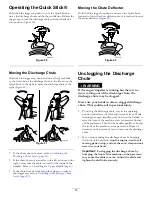
Hold the blue trigger cap down to use the Quick Stick to
move the discharge chute and the chute deflector. Release the
trigger cap to lock the discharge chute and chute deflector
into position (

Figure 40

).

Figure 40

Moving the Discharge Chute

Hold the blue trigger cap down and move the Quick Stick
to the left to move the discharge chute to the left; move the
Quick Stick to the right to move the discharge chute to the
right (

Figure 41

).

Figure 41

If the chute does not move, refer to

Adjusting the

Discharge Chute Latch (page 25)

.

If the chute does not turn as far to the left as it does to the
right, ensure that the cable is routed to the inside of the
handles. Refer to

1 Installing the Upper Handle (page 6)

.

If the chute does not lock into place when you release
the trigger cap, refer to

Adjusting the Discharge Chute

Latch (page 25)

.

Moving the Chute Deflector

Hold the blue trigger cap down and move the Quick Stick
forward to lower the chute deflector; move it rearward to raise
the chute deflector (

Figure 42

).

Figure 42

Unclogging the Discharge
Chute

WARNING

If the auger/impeller is running but there is no
snow coming out of the discharge chute, the
discharge chute may be clogged.

Never use your hands to clear a clogged discharge
chute. This could result in personal injury.

To unclog the discharge chute, stay in the operating
position and release the left hand (traction) lever. While
running the auger/impeller, push down on the handles to
raise the front of the machine a few centimeters (inches)
off the pavement. Then lift the handles quickly to bump
the front of the machine on the pavement. Repeat if
necessary until a stream of snow comes out the discharge
chute.

If you cannot unclog the discharge chute by bumping
the front of the machine,

stop the engine, wait for all

moving parts to stop, and use the snow cleanout tool;
never use your hand.

Important:

Unclogging the discharge chute by

bumping the front of the machine on the pavement
may cause the skids to move. Adjust the skids and
tighten the skid bolts securely.

18


Содержание 38805

Страница 1: ...r you need service genuine Toro parts or additional information contact an Authorized Service Dealer or Toro Customer Service and have the model and serial numbers of your machine ready Figure 1 identifies the location of the model and serial numbers on the machine Write the numbers in the space provided STOP G016493 1 Figure 1 1 Model and serial number location Model No Serial No This manual iden...

Страница 2: ...Engine 16 Operating the Traction Drive 16 Using the Wheel Clutch Levers 16 Operating the Speed Selector 17 Operating the Auger Impeller Drive 17 Operating the Quick Stick 18 Unclogging the Discharge Chute 18 Operating Tips 19 After Operation 19 Safety 19 Preventing Freeze up 19 Maintenance 20 Recommended Maintenance Schedule s 20 Maintenance Safety 20 Preparing for Maintenance 20 Checking the Engi...

Страница 3: ...harge opening Keep bystanders a safe distance from the machine Keep children out of the operating area and under the watchful care of a responsible adult other than the operator Never allow children to operate the machine Safety and Instructional Decals Important Safety and instruction decals are located near areas of potential danger Replace damaged decals 106 4525 Reorder part no 112 6633 1 Fast...

Страница 4: ... squeeze the lever to engage release the lever to disengage 4 Cutting dismemberment hazard impeller do not place your hand in the chute stop the engine before leaving the operator s position use the tool to clear the chute 6 Thrown object hazard keep bystanders a safe distance from the snowthrower 8 Right turn control 131 6487 1 Engine stop 3 Fast 2 Slow x 3 1 2 3 4 5 120 9805 120 9805 1 Insert th...

Страница 5: ... Install the wheel clutch cable ends 3 No parts required Install the traction control linkage Carriage bolts 2 4 Locknuts 2 Install the chute control rod 5 Cable tie 1 Connect the wire to the headlight 6 No parts required Fill the engine with oil 7 No parts required Check the tire pressure 8 No parts required Check the skids and scraper 9 No parts required Check the operation of the traction drive...

Страница 6: ... the upper handle legs and ensure that the cables and the wire for the headlight are not pinched between the handle sections Figure 3 1 Cables 2 Secure the upper handle with 4 handle bolts 4 curved washers and 4 locknuts from the loose parts bag Figure 4 Figure 4 2 Installing the Wheel Clutch Cable Ends No Parts Required Procedure 1 Unwrap the cable ends from the lower handle Figure 5 Figure 5 2 R...

Страница 7: ...ap between the bottom of the handle and the wheel clutch lever end Figure 9 Figure 9 Note The gap should be approximately the thickness of a pencil 1 4 inch or 6 mm If it is greater loosen the cable clamp nut slide the cable jacket up slightly tighten the cable clamp nut and check the gap again 6 Repeat steps 2 through 5 for the other cable 3 Installing the Traction Control Linkage No Parts Requir...

Страница 8: ... control rod with the outer washer and a hairpin cotter you previously removed Note For easier installation look down through the opening in the speed selector Figure 13 Figure 13 1 Speed selector 4 Installing the Chute Control Rod Parts needed for this procedure 2 Carriage bolts 2 Locknuts Procedure 1 Unwrap the Quick Stick and rotate it so that it is upright and in the center 2 Hold the blue tri...

Страница 9: ...he loose parts bag Figure 16 g018657 Figure 16 1 Cable clip 2 Deflector cable 7 Hold the blue trigger cap down and rotate the Quick Stick in a circle to ensure that the chute and deflector operate smoothly 5 Connecting the Wire to the Headlight Parts needed for this procedure 1 Cable tie Procedure 1 Insert the wire connector on the loose end of the wire straight into the back of the headlight unti...

Страница 10: ...ted Figure 18 Engine Oil Capacities Model Engine Oil Capacity 38805 0 53 to 0 59 L 18 to 20 oz 1 Remove the dipstick and slowly pour oil into the oil fill tube to raise the oil level to the Full mark on the dipstick Do not overfill Figure 19 Refer to page Figure 19 2 Install the dipstick securely Note Do not spill oil around the oil fill tube oil could leak onto traction parts and cause the tracti...

Страница 11: ...e the traction lever and stop the engine B Disconnect the trunnion from the speed selector lever Figure 11 C Turn the trunnion downward clockwise on the speed control rod Figure 11 D Connect the trunnion to the speed selector lever Figure 11 4 Release the traction lever 5 Move the speed selector to the Position F1 refer to Operating the Speed Selector 6 Squeeze the left hand traction lever to the ...

Страница 12: ...that can get caught in moving parts Wear slip resistant footwear that will improve footing on slippery surfaces Always wear safety glasses or eye shields during operation or while performing an adjustment or repair to protect eyes from foreign objects that may be thrown from the machine Thoroughly inspect the area where the machine is to be used and remove all doormats sleds boards wires and other...

Страница 13: ...chine When not actively clearing snow disengage power to the rotor blades Use extension cords and receptacles as specified by the manufacturer for all machines with electric starting motors Do not attempt to clear snow from a gravel or crushed rock surface This product is intended for use only on paved surfaces Do not use the machine on a roof Never attempt to make any adjustments while the engine...

Страница 14: ...Refer to Checking the Engine Oil Level page 21 2 Turn the fuel shutoff valve 1 4 turn counterclockwise to open it Figure 27 G016512 Figure 27 3 Insert the ignition key all the way in Figure 28 1 G016498 Figure 28 1 Ignition key 4 Firmly push in the primer with your thumb 3 times holding the primer in for a second before releasing it each time Figure 29 G016494 Figure 29 14 ...

Страница 15: ...rical cord before using the machine If the cord is damaged do not operate the machine Replace or repair the damaged cord immediately Contact an Authorized Service Dealer for assistance Important To prevent damaging the electric starter run it in short cycles 5 seconds on 5 seconds off no more than 10 times If the engine still does not start take the machine to an Authorized Service Dealer for serv...

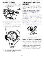
Страница 16: ... Drive Operation page 11 for more information Important If the machine moves when the traction lever is in the released position check the traction cable refer to Checking and Adjusting the Traction Cable page 22 or take the machine to an Authorized Service Dealer for service Important To operate the traction drive you must operate the machine with the self propel feature engaged Refer to Freewhee...

Страница 17: ...o change speeds release the traction lever and shift the speed selector lever to the desired position Figure 38 The lever locks in a notch at each speed selection Figure 38 Operating the Auger Impeller Drive 1 To engage the auger impeller drive squeeze the right hand auger impeller lever to the handgrip Figure 39 Figure 39 2 To stop the auger and impeller release the right hand lever Important Whe...

Страница 18: ... the Quick Stick forward to lower the chute deflector move it rearward to raise the chute deflector Figure 42 Figure 42 Unclogging the Discharge Chute WARNING If the auger impeller is running but there is no snow coming out of the discharge chute the discharge chute may be clogged Never use your hands to clear a clogged discharge chute This could result in personal injury To unclog the discharge c...

Страница 19: ...now If the engine slows down under a load or the wheels slip shift the machine into a lower gear If the front of the machine rides up shift the machine into a lower gear If the front continues to ride up lift up on the handles After Operation Safety Never store the machine with fuel in the fuel tank inside a building where ignition sources are present such as hot water heaters space heaters or clo...

Страница 20: ...0 psi 116 137 kPa Run the engine to dry out the fuel tank and the carburetor at the end of the season Have an Authorized Service Dealer inspect and replace the traction drive belt and or the auger impeller drive belt if necessary Important You can find more information about maintaining and servicing your machine at www Toro com Maintenance Safety Read the following safety precautions before perfo...

Страница 21: ...h skids to the auger sides until the skids slide up and down easily Figure 44 Figure 44 1 1 3 cm 1 2 inch 3 Support the side plates so that they are at least 1 3 cm 1 2 inch above a level surface Important The auger blades must be supported above the ground by the skids 4 Ensure that the scraper is 3 mm 1 8 inch above and parallel to a level surface Note If the pavement is cracked rough or uneven ...

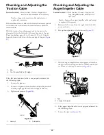
Страница 22: ...djusted do the following steps 1 Loosen the jam nut 2 Loosen or tighten the turnbuckle to adjust the pin until it is the proper gap from the front edge of the slot 3 Tighten the jam nut Figure 46 Figure 46 1 Jam nut 2 Turnbuckle Checking and Adjusting the Auger Impeller Cable Service Interval After the first 2 hours Inspect the auger impeller cable and adjust it if necessary Yearly Inspect the aug...

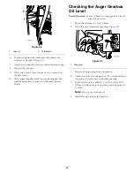
Страница 23: ...ler Checking the Auger Gearbox Oil Level Service Interval Yearly Check the auger gearbox oil and add oil if necessary 1 Move the machine to a level surface 2 Clean the area around the pipe plug Figure 50 1 G016782 Figure 50 1 Pipe plug 3 Remove the pipe plug from the gearbox 4 Check the oil level in the gearbox The oil should be at the point of overflowing at the filler opening 5 If the oil level ...

Страница 24: ...local recycling center 4 Install the oil drain cap 5 Fill the crankcase with oil Refer to 6 Filling the Engine with Oil page 9 Lubricating the Hex Shaft Service Interval Yearly Lubricate the hex shaft Lightly lubricate the hex shaft yearly with automotive engine oil Figure 53 Figure 53 1 Hex shaft 3 Rubber wheel 2 Aluminum friction plate Important Do not get oil on the rubber wheel or the aluminum...

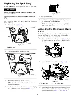
Страница 25: ...ch as shown in Figure 57 Figure 57 1 0 76 mm 0 030 inch 5 Install the new spark plug tighten it firmly and attach the ignition wire to the spark plug Note Ensure the ignition wire snaps completely into place on the spark plug Adjusting the Discharge Chute Latch If the discharge chute does not lock into the desired position or does not unlock so that you can move it to another position adjust the d...

Страница 26: ... Dealer replace the belt Replacing the Headlight Bulb Use a GE 899 37W halogen light bulb Do not touch the bulb with your hands or allow dirt or moisture to come into contact with the bulb 1 Remove the wire connector from the back of the headlight Figure 61 Figure 61 2 Turn the base of the bulb counterclockwise until it stops Figure 62 Figure 62 3 Remove the bulb straight out from the back of the ...

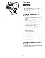
Страница 27: ...of fuel 4 Prime the engine and start it again 5 Allow the engine to run until it stops When you can no longer start the engine it is sufficiently dry 6 Stop the engine and allow it to cool 7 Remove the ignition key 8 Clean the machine thoroughly 9 Touch up chipped surfaces with paint available from an Authorized Service Dealer Sand affected areas before painting and use a rust preventative to prev...

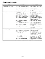
Страница 28: ... the wire to the spark plug 7 The spark plug is pitted fouled or the gap is incorrect 7 Check the spark plug and adjust the gap if necessary Replace the spark plug if it is pitted fouled or cracked 8 The fuel vent cap is restricted 8 Remove the vent restriction or replace the fuel cap The engine does not start or starts hard 9 The engine oil level in the engine crankcase is too low or too high 9 A...

Страница 29: ... the auger impeller drive belt refer to www Toro com for servicing information or take the machine to an Authorized Service Dealer The engine runs but the machine discharges snow poorly or not at all 7 The auger impeller drive belt is worn or broken 7 Replace the auger impeller drive belt refer to www Toro com for servicing information or take the machine to an Authorized Service Dealer The discha...

Страница 30: ...pplication for certification The warranty period begins on the date the small off road engine equipment is delivered to an ultimate purchaser The warranted period is two years Subject to certain conditions and exclusions as stated below the warranty on evaporative emissions related parts is as follows 1 Any warranted part that is not scheduled for replacement as required maintenance in the written...

Страница 31: ...ction System Air cleaner Intake manifold Crankcase vent and line s Purge line and fittings 3 Ignition System Spark plug s and wire s Magneto ignition system 4 Catalytic Exhaust System Catalytic converter Exhaust manifold Air injector system and valve s 5 Miscellaneous Items Used in Emission Control System Valves switches and linkages Connectors fittings and brackets 374 0299 Rev A ...

Страница 32: ...re is no other express warranty except for special emission system coverage and engine warranty coverage on some products This express warranty does not cover the following Cost of regular maintenance service or replacement of wear parts such as blades rotor blades paddles scraper blades belts fuel lubricants oil changes spark plugs light bulbs cable linkage or brake adjustments Any product or par...

Отзывы: