background image

10

1

2

3

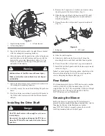
Figure 5

1.

Right mounting bracket

2.

Left mounting bracket

3.

Lift arm bracket

5. Secure the ball joint mount to the right blower bracket

with the cutting unit mounting fasteners.

6. Have a helper carefully push down on the left push arm

until the holes in the ball joint mount line up with the
holes in the castor arm. Immediately slide a 4 x 4 in.
block of wood between the top of the push arm and
underside of the chassis.

Sudden release of the lift arm could cause injury.

Make sure that the wooden block does not slip out
accidentally.

Warning

7. Secure the ball joint mount to left blower bracket with

the cutting unit mounting fasteners.

8. Carefully remove the wood block holding the push arm

down.

9. Pivot the blower rearward and secure the lift bracket to

the T-bar on the traction unit with the lift arm bracket
and pin.

Installing the Drive Shaft

Danger

The PTO shaft rotates with enough force to cause
serious injury.

Do not start the engine and engage the PTO lever
when the PTO shaft is not connected to the blower
gear box.

1. Remove the 5 capscrews, 6 washers, and nut securing

the belt guard to the blower frame (Fig. 6).

2. Slide the drive shaft onto the traction unit PTO shaft

(Fig. 6). Align the mounting holes in each shaft and
slide them together.

3. Secure them with a roll pin and 2 capscrews and nuts

(Fig. 6).

1

2

Figure 6

1.

Belt guard

2.

PTO shaft

4. Slide the shafts together.

5. Slide drive shaft onto the blower shaft. Align the

mounting holes in each shaft and slide them together.

6. Secure them with a roll pin and 2 capscrews and nuts.

7. Install the belt shaft guard with the fasteners previously

removed (Fig. 6).

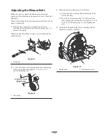
Note: To ensure proper blower operation, check/adjust the
blower belt tension after the first 20 hours of operation;
refer to Adjusting the Blower Belt, page 13.

Rear Ballast

The Groundsmaster 300 series 2WD traction unit complies
with the ANSI B71.4-1990 Standard when (5) 35 lb.
weights (Part No. 24-5790) are installed. Order two Weight
Kits, Part No. 24-5780 and one Weight Kit, Part No.
24-5790 from your Toro Distributor.

Greasing the Blower

Before the blower is operated, the PTO shaft must be
greased to ensure proper lubricating characteristics; refer to
Greasing the Blower in the Maintenance section;
page NO TAG. Failure to properly grease the unit will
result in premature failure of critical parts.

Содержание 30855

Страница 1: ...Operator s Manual English EN Form No 3350 248 Debris Blower Groundsmaster 300 Series Attachment Model No 30855 Serial No 230000001 and Up...

Страница 2: ...thers avoid personal injury and even death Danger Warning and Caution are signal words used to identify the level of hazard However regardless of the hazard be extremely careful Danger signals an extr...

Страница 3: ...possibly be deadly The maximum seating capacity is one person Never carry passengers Sit on the seat when starting the engine and operating the machine This product may exceed noise levels of 85 dB A...

Страница 4: ...l pressure in the system must be relieved by stopping the engine and lowering the blower to the ground If the engine must be running to perform a maintenance adjustment keep hands feet clothing and ot...

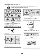
Страница 5: ...of hand or foot wait for moving parts to stop 98 3111 1 Point of rotation 105 0709 1 Entanglement hazard belt place the guard over the belt and stay away from moving parts 98 3113 1 Warning stop the e...

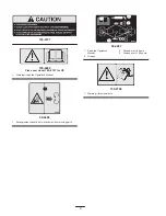
Страница 6: ...0707 for CE 1 Warning read the Operator s Manual 99 4486 1 Entanglement hazard belt stay away from moving parts 99 4487 1 Read the Operator s Manual 2 Grease 3 Grease every 8 hours 4 Grease every 100...

Страница 7: ...pper Increasing scroll from cutoff Fan drive PTO driven A 3VX banded belt drive to fan Final drive ratio of 1 5 1 with a over running clutch in belt drive pulley Fan shaft rotates on greaseable ball b...

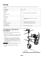
Страница 8: ...ing position Installing the Castor Wheel Assemblies The castor wheel assemblies are installed upside down on the debris blower for shipping 1 Remove the tensioning caps from the spindle shafts and sli...

Страница 9: ...oro ball joint mounts Part No 21 3050 and 21 3020 Note Retain the fasteners for future installation of cutting unit or attachment 2 The right and left ball joints are properly adjusted when the distan...

Страница 10: ...rews 6 washers and nut securing the belt guard to the blower frame Fig 6 2 Slide the drive shaft onto the traction unit PTO shaft Fig 6 Align the mounting holes in each shaft and slide them together 3...

Страница 11: ...crease the PTO speed to 1800 RPM 5 Practice blowing material It is advisable to blow the same direction the wind is blowing to prevent material from blowing back into the cleared area Transporting the...

Страница 12: ...fan shaft bearings Fig 8 and 9 must be lubricated after every 8 hours of operation with a No 2 Lithium based grease Castor Wheels Under normal conditions grease the 2 wheels and 2 wheel pivot tubes F...

Страница 13: ...the belt 1 Figure 11 1 Belt guard 2 A new belt is properly tensioned when the idler spring body is extended to a length of 3 1 4 to 3 1 2 in 83 89 mm Fig 12 3 1 4 to 3 1 2 in 83 89 mm 1 Figure 12 1 Id...

Страница 14: ...uilt up on the fan blades 2 Clean out any build up on the inside of the housing 3 The RPM of the PTO shaft is too fast 3 Reduce the PTO speed to 540 RPM There is lack of adequate air flow 1 The air sl...

Страница 15: ...clean the blower The fan housing should be free of dirt leaves and debris 2 Lubricate all grease fittings Wipe off any excess lubricant 3 Place a light coat of grease on the splines of the PTO adapter...

Страница 16: ...contamination use of unapproved coolants lubricants additives or chemicals etc Normal wear and tear items Normal wear and tear includes but is not limited to damage to seats due to wear or abrasion wo...

Отзывы: