


7
Setup
General
Refer to illustrated parts list for details of parts used in
assembling and installing the Rotary Hydraulic Broom.
Note:
Determine the left and right sides of the machine
from the normal operating position.
Note:
See Pump Mounting for installing brooms on traction
units with different PTO shaft lengths.
Head and Tank Assembly
1.
Extend stands on tank / mount frame and retain with
latch pins.
2.
Align broom head pivot with tank / mount frame. Insert
pivot pin and retain with cotter pin.
3.
Connect hydraulic hoses from motor to pump and inlet
filter. Route hydraulic hose to pump through bottom
clamp at lift stop. Route hydraulic hose to inlet filter by
looping around right side of lift stop through upper
clamp. Pull hoses snug from pump and inlet filter to
clamps and secure.
4.
Pivot broom head and/or extend manual swivel tube
until it can be attached to the broom head frame. Secure
to broom head frame with the capscrew, spacer and
locknut. Attach the manual swivel shaft to the tank I
frame mount with the capscrew and locknut.
Electric Swivel Option
(Model No. 30728)
1.
Pivot broom head until the actuator can be attached to
the broom head frame.
2.
Secure motor end (motor facing right) of actuator to
broom head frame with the capscrew and locknut.
Attach the shaft end of the actuator to the tank / frame
mount with the capscrew and locknut.
Broom Control Box and Wiring
(Electric Swivel Option)
1.
Attach broom control box to the steering column with
clamp and nuts about 6 inches below steering wheel.
2.
Route the actuator wire through the steering column and
connect to actuator.
3.
Remove the instrument panel cover.
4.
Route the power wires through the steering column and
frame to the instrument panel and attach the negative
wire (black) to the common ground terminal and the
positive wire (red) to the rear terminal of the fuel gauge.
Reinstall cover.
Install the Push Arm
Note:
Ball Joint Mount L. H. (21–3050), which is used
with the side discharge deck, is required before proceeding
with installation.
1.
Position traction unit on level surface and shut the
engine off.
2.
Move broom into position in front of traction unit.
Since the right hand push arm is spring loaded to
about 100 pounds and left hand push arm is spring
loaded to about 150 pounds, a helper is needed to
push the push arm down. Sudden release of the
push arm could cause injury.
Warning
3.
Have a helper carefully push down on right hand push
arm until holes in ball joint mount line up with holes in
broom mount. Attach ball joint mount to broom mount
with capscrews, flat washers and flange nuts but don’t
tighten.
4.
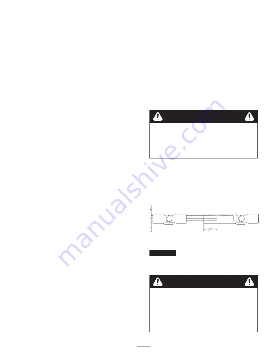
Align and insert the traction unit PTO splined shaft into
the broom PTO receiver (Fig. 1).
Figure 1
Important
Ensure 2 inches of PTO shaft engages with
implement shaft (Fig. 1). If not, the implement shaft must
be replaced with the appropriate length of shaft available
from the Toro Parts Department.
•
Improper PTO operation could result in failure
of the PTO drive
.
•
Failure of the PTO drive could damage the
implement, traction unit, or result in serious
personal injury or death.
•
Read the traction unit and implement manuals
and be familiar with PTO operation.
Warning
Содержание 30743
Страница 15: ...15...


