


15
CONTROLS
Seat
(Fig. 12) - Pull seat adjusting lever (right side)
outward,slide seat fore or aft to desired position and
release lever to lock seat in position. Seat moves 5.9
in.(15 cm) fore and aft in 19/32 in. (15 mm) increments.
Knob at lower center provides infinitely variable weight
adjustment from 110 - 285 lb (49.9 - 129.3 kg).
Figure 12
1. Seat Adjusting Lever
2. Weight Adjusting Knob
3. Weight Indicator
Seat height adjusts vertically to three positions. To
raise: lift seat to first or second click stop; to lower: lift
seat to highest position, then lower to lowest position.
Arm rests pivot up and down.
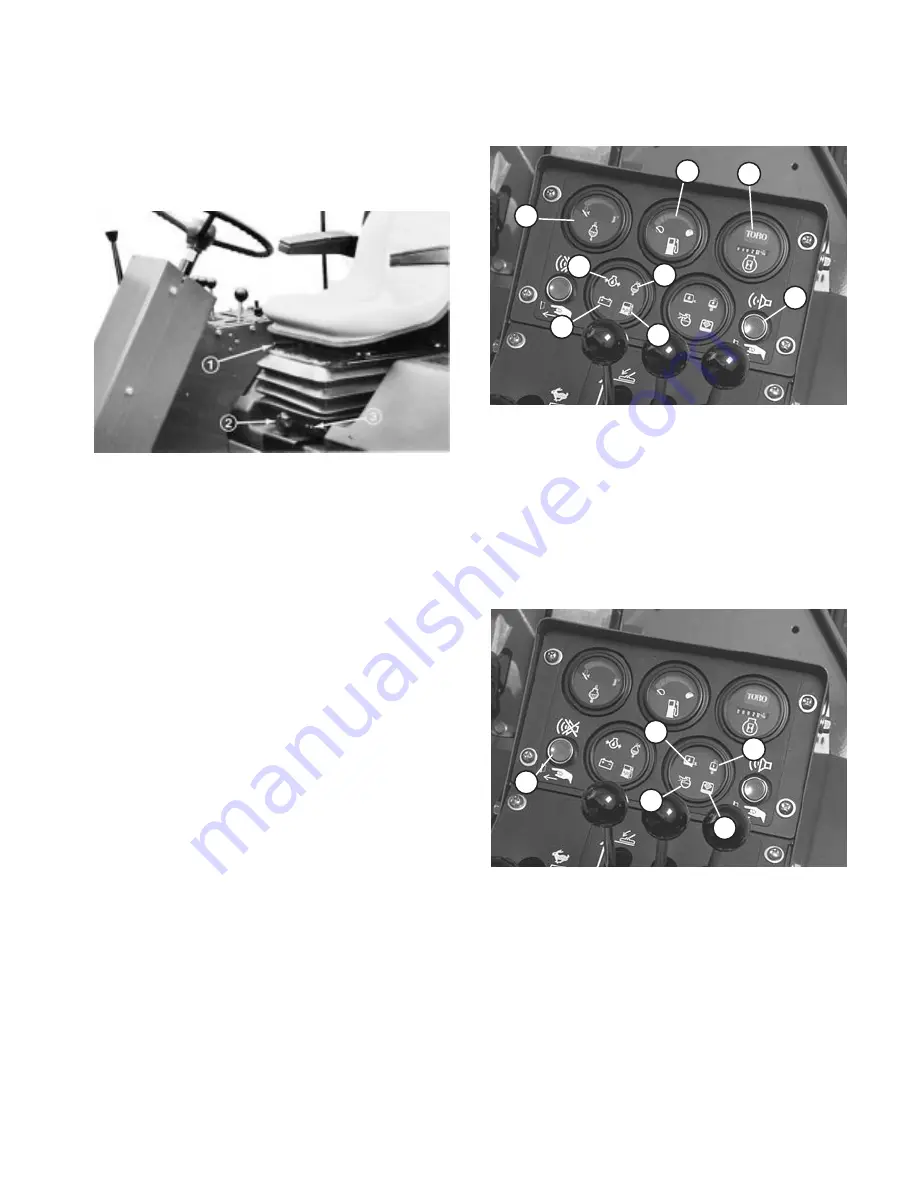
Warning Light Check Switch
(Fig. 13) - Before
beginning operation, press switch button. All lights on
control panel should light. If a light fails to illuminate,
there is an electrical malfunction requiring immediate
repair.
Engine Oil Pressure Warning
(Fig. 13) -
Dangerously low engine oil pressure is indicated by
both a warning indicator light and audible signal. When
this occurs, stop the engine immediately to keep
possible engine damage minimal.
No Charge Warning
(Fig. 13) - No charge to the
batteries is indicated by a warning indicator light and
audible signal.
Fuel System Warning
(Fig. 13) - A warning indicator
light and audible signal warn of water in the fuel and
need for service.
Coolant Temperature Warning
(Fig. 13) - If engine
coolant temperature exceeds 215
F (101.7
C), a
warning indicator light illuminates and audible signal
sounds. If coolant temperature exceeds 230
F (110
C), the engine automatically shuts down. Switch resets
automatically when system and engine cools down.
Hour Meter
(Fig. 13) - Registers accumulated hours
of engine operation. Useful for determining intervals for
service maintenance and lubrication.
Coolant Temperature Gauge
(Fig. 13) - Indicates
temperature of system coolant.
Fuel Gauge
(Fig. 13) - Indicates quantity of fuel in fuel
tank.
Figure 13
5. Engine Oil Pressure Warning
6. No Charge Warning
7. Fuel System Warning
8. Warning Light Check Switch
1. Coolant Temperature
Gauge
2. Fuel Gauge
3. Hour Meter
4. Coolant Temperature
Warning
1
2
3
4
5
6
7
8
Hydraulic Oil Temperature Warning
(Fig. 14) - A
warning indicator light and audible signal warn of
excessively high hydraulic oil temperature.
Figure 14
1. Hydraulic Oil Level Warning
2. Hydraulic Oil Temperature Warning
3. Hydraulic Oil Filter Warning
4. Air Cleaner Warning
5. Alarm silence Button
1
2
3
4
5
Hydraulic Oil Filter Warning
(Fig. 14) - A warning
indicator light and audible signal warn the filter is
clogged and in need of service.
Hydraulic Oil Level Warning
(Fig. 14) - A warning
indicator light and audible signal warn of low hydraulic
oil level. If oil level drops further, the engine will
automatically be stopped. Engine cannot be restarted
until oil supply is brought to a safe level.


