18
4. Select a hole so that the gage wheel is positioned to the
nearest corresponding height-of-cut desired (Fig. 11).
5. Install the stud nut and washer (Fig. 11).
6. Repeat the adjustment on the other gage wheels.
Positioning the Seat
The seat can move forward and backward. Position the seat
where you have the best control of the machine and are
most comfortable.
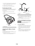
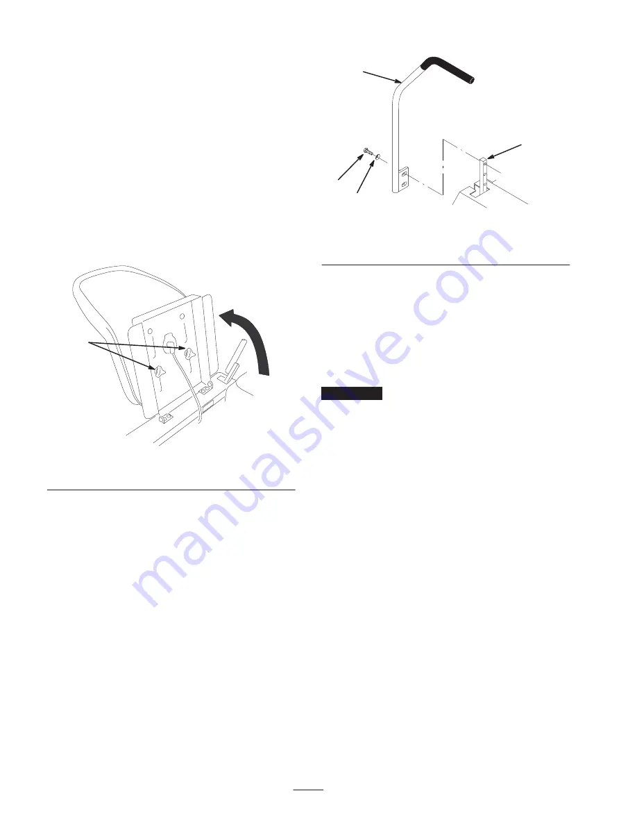
1. Raise the seat and loosen the adjustment knobs
(Fig. 12).
2. Move the seat to the desired position and tighten the
knobs.
1
m–5163
Figure 12
1.
Adjustment knobs
Adjusting the Motion Control
Levers
The motion control levers can be adjusted higher or lower
for maximum operator comfort.
1. Remove the 2 screws and curved washers holding the
control lever to the control arm shaft (Fig. 13).
m–5215
1
2
3
4
Figure 13
1.
Control lever
2.
Screw
3.
Curved washer
4.
Control arm shaft
2. Move the control lever to the next set of holes. Secure
the lever with the 2 screws and curved washers. The
cupped side of the washer should be toward the control
arm shaft (Fig. 13).
3. Repeat the adjustment on the other control lever.
Pushing the Machine by Hand
Important
Always push the machine by hand. Never
tow the machine because damage may occur.
To Push the Machine
1. Disengage the PTO and move the control levers to the
neutral locked position and apply the parking brake.
2. Stop the engine, remove the key, and wait for all
moving parts to stop before leaving the operating
position.
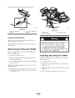
3. Pull the two bypass levers up and push them until the
washer on the rod passes through the slot. Push the
levers down to lock them in place (Fig. 14).
Содержание 18-52ZX TimeCutter
Страница 7: ...7 Slope Chart ...
Страница 8: ...8 ...

