


33
4.
Fill the hydraulic tank with approximately 4.5 gallons
of hydraulic oil; refer to Checking the Hydraulic
System, page 18.
5.
Start the machine and run it at idle for 3 to 5 minutes to
circulate the fluid and remove any air trapped in the
system. Stop the machine and recheck the fluid level.
6.
Dispose of the used oil properly.
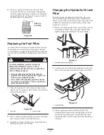
Checking the Hydraulic Lines
and Hoses
Hydraulic fluid escaping under pressure can
penetrate skin and cause injury.
•
Make sure all hydraulic fluid hoses and lines are
in good condition and all hydraulic connections
and fittings are tight before applying pressure to
the hydraulic system.
•
Keep your body and hands away from pin hole
leaks or nozzles that eject high pressure
hydraulic fluid.
•
Use cardboard or paper to find hydraulic leaks.
•
Safely relieve all pressure in the hydraulic
system before performing any work on the
hydraulic system.
•
Seek immediate medical attention if fluid is
injected into skin.
Warning
Check the hydraulic lines and hoses daily for leaks, kinked
lines, loose mounting supports, wear, loose fittings, weather
deterioration, and chemical deterioration. Make all
necessary repairs before operating.
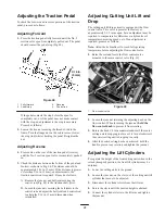
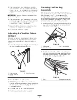
Adjusting the Brakes
A brake adjustment rod is located on each side of the
machine so that the brakes can be equally adjusted. Adjust
the brakes as follows:
1.
Transport the machine and depress the brake pedal; both
wheels should lock equally.
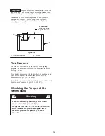
Testing the brakes in a confined area where others
are present could cause injury.
Always check the brakes in a wide, open-spaced,
flat area which is free of other persons and
obstructions before and after adjustment.
Caution
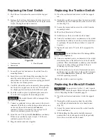
2.
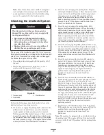
If the brakes do not lock equally, disconnect the brake
rods by removing the cotter pin and clevis pin (Fig. 43).
m–5100
1
2
3
4
Figure 43
1. Clevis pin and cotter pin
2. Jam nut
3. Clevis
4. Brake shaft
3.
Loosen the jam nut and adjust the clevis accordingly
(Fig. 43).
4.
Assemble the clevis to the brake shaft (Fig. 43).
5.
Check the amount of free travel of the brake pedal when
the adjustment is completed. There should be 1/2 to
1 in. (13 to 26 mm) travel before the brake shoes make
contact with the brake drums. Readjust, if necessary, to
achieve this setting.
6.
Transport the machine and depress the brake pedal; both
brakes should lock equally. Readjust, if necessary.
7.
It is recommended that the brakes be burnished
annually; refer to Break-In Period, page 22.
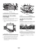
Adjusting the Rear Camshaft
A camshaft misaligned with the valve bank may cause the
following:
•
No increase in ground speed in the No. 2 (transport)
traction selection
•
The mow pedal will not stay depressed (in detent)
without foot pressure.
•
Slow lift of the cutting units
•
Slow or no drive to the cutting units
If one or more malfunctions occur, loosen the rear camshaft
mounting capscrews (Fig. 44) and relocate the cam shaft
until
the condition is corrected. Retighten the capscrews.
Important
Readjust the mow/lift switch and the lift and
mow pedal height when the camshaft adjustment is
completed.
Содержание 04351 Greensmaster 3050
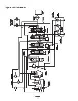
Страница 40: ...40 Hydraulic Schematic ...
Страница 46: ...46 ...