


Greensmaster Flex 18/21
Page 6 – 9
Chassis and Controls
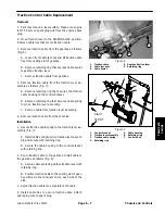
Throttle Cable Replacement
Removal
1. Park machine on a level surface. Make sure engine
is OFF. Remove spark plug wire from the spark plug.
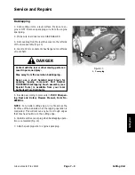
2. Remove cable tie that secures throttle cable.
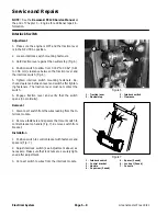
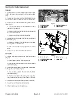
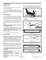
3. Remove throttle cable from the engine governor link-
age as follows (Fig. 10):
A. Unscrew throttle cable screw enough to release
the throttle cable from the nut in the governor lever.
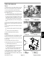
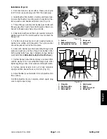
B. Remove cap screw and flange nut that secure
cable clamp to traction unit frame (Fig. 11). Locate
and retrieve three (3) washers from under clamp.
C. Pull throttle cable clear of the nut in the governor
lever.
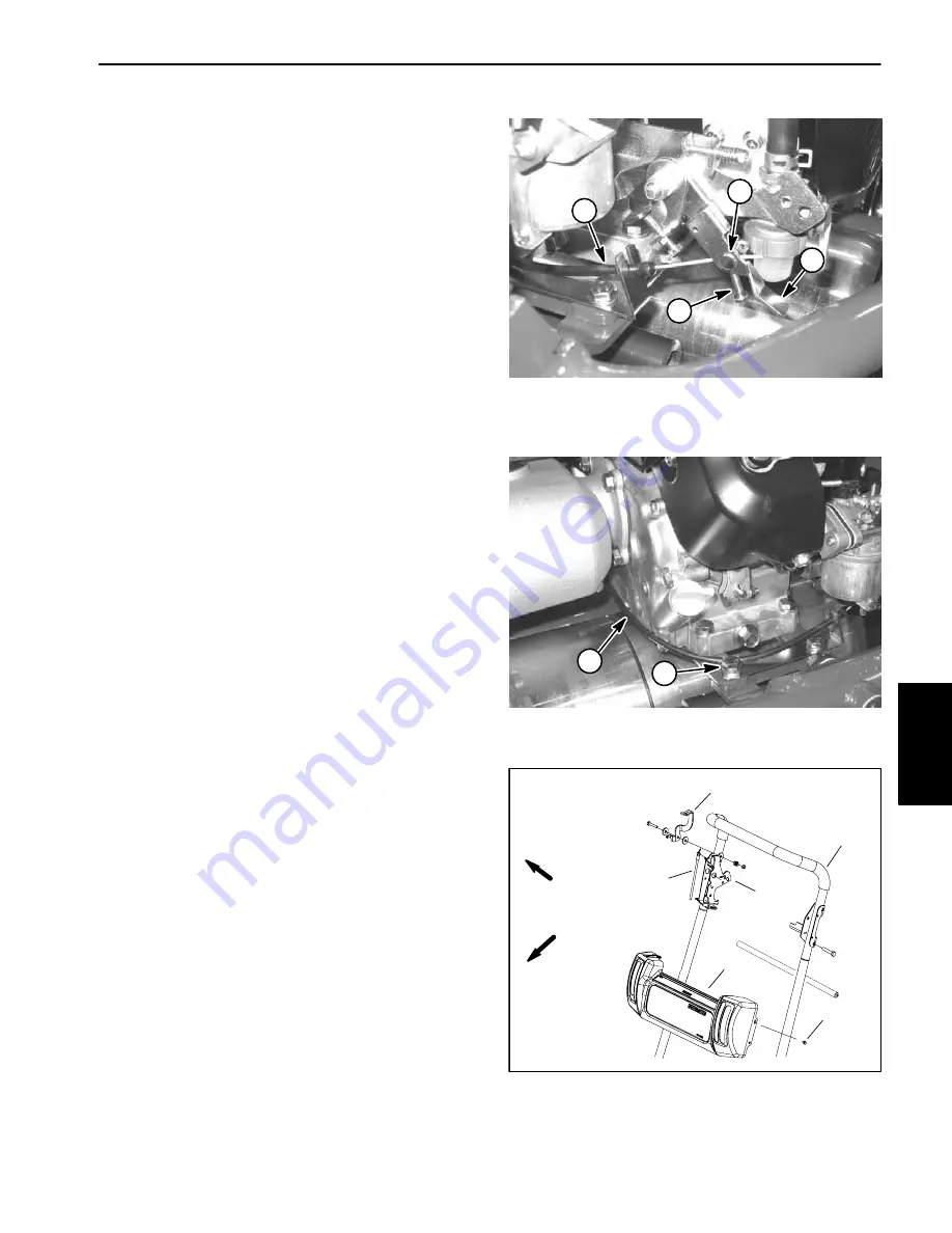
4. Remove four (4) screws securing the console to the
handle and move console forward and away from the
handle.
5. Remove throttle cable from the throttle lever assem-
bly (Fig. 12):
A. Unsnap the cable housing from the control brack-
et.
B. Unhook cable end from throttle lever.
6. Remove throttle cable from the machine.
Installation
1. Connect throttle cable to the throttle lever. Snap
throttle cable housing to the control bracket (Fig. 12).
2. Position console to handle and secure console with
four (4) screws.
3. Route throttle cable to the governor lever.
4. Install cable to the governor lever as follows (Fig. 10):
A. Insert throttle cable into the nut.
B. Tighten throttle cable screw to hold cable in the
nut. Do not fully tighten screw.
C. Position three (3) washers and cable clamp to
frame. Secure with cap screw and flange nut.
5. Adjust throttle cable (see Throttle Cable Adjustment
in the Adjustments section of Chapter 3 – Engine).
6. Secure throttle cable with cable tie. Attach spark plug
wire to spark plug.
Figure 10
1. Governor
lever
2. Throttle
cable
3. Throttle cable screw
4. Throttle cable nut
1
2
4
3
1. Throttle
cable
2. Cable
clamp
Figure 11
1
2
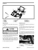
1. Handle
2. Throttle
cable
3. Throttle
lever
4. Control
bracket
5. Console
6. Screw (4 used)
Figure 12
1
3
2
FRONT
RIGHT
4
5
6
Chassis and
Controls
Содержание 04022 Greensmaster Flex 21
Страница 2: ...Greensmaster Flex 18 21 This page is intentionally blank ...
Страница 4: ...Greensmaster Flex 18 21 This page is intentionally blank ...
Страница 10: ...0 09375 Greensmaster Flex 18 21 Page 2 2 Product Records and Maintenance Equivalents and Conversions ...
Страница 28: ...Greensmaster Flex 18 21 Traction and Reel Drive System Page 4 4 This page is intentionally blank ...
Страница 48: ...Greensmaster Flex 18 21 Traction and Reel Drive System Page 4 24 This page is intentionally blank ...
Страница 58: ...Greensmaster Flex 18 21 Page 5 10 Electrical System This page is intentionally blank ...
Страница 83: ...Greensmaster Flex 18 21 Page 7 13 Cutting Unit This page is intentionally blank Cutting Unit ...
Страница 85: ...Greensmaster Flex 18 21 Page 7 15 Cutting Unit This page is intentionally blank Cutting Unit ...
Страница 111: ...Greensmaster Flex 18 21 Groomer Page 8 15 This page is intentionally blank Groomer ...


