


Greensmaster Flex 18/21
Traction and Reel Drive System
Page 4 – 21
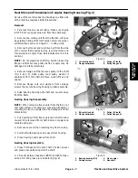
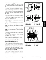
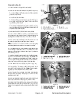
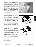
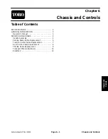
8. If traction band is replaced, the new band will have
an ink mark on the upper end of the band (Fig. 28).
9. Carefully fit traction shaft with band to the planetary
assembly and gearbox base taking care not to distort
traction band. Traction band should easily slide over
traction drum during installation. If traction band is im-
properly placed on the traction shaft or if the band is dis-
torted, it will not fit easily on the drum. Check that
planetary assembly is free to rotate with band installed.
Note: On Flex 21, if gearbox is still attached to engine,
traction lever on engine side of gearbox should be instal-
led onto traction shaft is shaft is installed into gearbox.
10.Rotate differential shaft to verify that all gears and
shafts are meshed properly.
11. Use dowel pins to position gasket to gearbox base.
12.Lubricate short differential axle shaft. Position gear-
box cover to shafts and fit cover to the gearbox base.
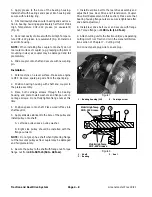
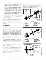
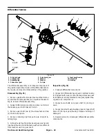
13.Position drive shaft plate to gearbox with three fas-
teners: two socket head screws (shorter) and one cap
screw with lock washer. Install four socket head screws
(longer) and washers in remaining holes in gearbox cov-
er. Torque gearbox fasteners from 120 to 140 in–lb
(13.6 to 15.8 N–m) in the sequence shown in Figure 29.
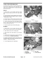
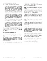
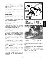
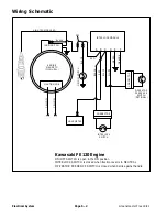
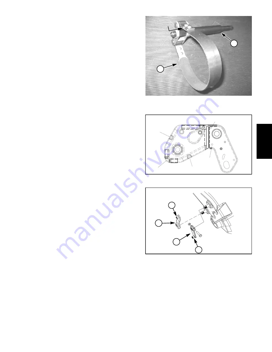
14.Place traction drive lever onto gearbox shaft noting
location of alignment splines on shaft and lever. Mount
traction lever with cable boss outward (Fig. 30). Secure
lever with cap screw and lock nut. Parking brake lever
installation should be done with cable attached to lever
as gearbox is being installed on machine.
15.Check gearbox operation:
A. Engage and disengage clutch, brake band and
traction band. Check for smooth engagement.
B. Turn one differential axle shaft and check that
other shaft rotates in opposite direction.
C. If smooth operation is not detected, correct prob-
lem before completing assembly.
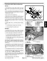
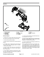
16.Install reel drive assembly to the gearbox (Fig. 22):
A. Apply antiseize lubricant to the bore of the reel
drive pulley. Place woodruff key in gearbox shaft and
slide pulley and pulley washer onto shaft. Thread
flange nut onto shaft.
B. Position reel drive belt over pulleys and properly
tension belt (see Transmission Coupler Drive Belt
Adjustment in this section).
C. Tighten flange nut to secure pulley.
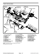
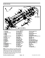
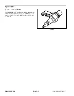
1. Traction
shaft
2. Traction
band
Figure 28
MARK LOCATION
2
1
Figure 29
3
1
4
5
2
6
1. Traction drive lever
2. Parking brake lever
3. Cable mounting boss
Figure 30
3
3
2
1
Traction and Reel
Drive System
Содержание 04022 Greensmaster Flex 21
Страница 2: ...Greensmaster Flex 18 21 This page is intentionally blank ...
Страница 4: ...Greensmaster Flex 18 21 This page is intentionally blank ...
Страница 10: ...0 09375 Greensmaster Flex 18 21 Page 2 2 Product Records and Maintenance Equivalents and Conversions ...
Страница 28: ...Greensmaster Flex 18 21 Traction and Reel Drive System Page 4 4 This page is intentionally blank ...
Страница 48: ...Greensmaster Flex 18 21 Traction and Reel Drive System Page 4 24 This page is intentionally blank ...
Страница 58: ...Greensmaster Flex 18 21 Page 5 10 Electrical System This page is intentionally blank ...
Страница 83: ...Greensmaster Flex 18 21 Page 7 13 Cutting Unit This page is intentionally blank Cutting Unit ...
Страница 85: ...Greensmaster Flex 18 21 Page 7 15 Cutting Unit This page is intentionally blank Cutting Unit ...
Страница 111: ...Greensmaster Flex 18 21 Groomer Page 8 15 This page is intentionally blank Groomer ...


