5.
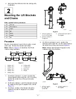
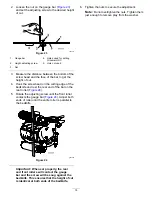
On lift arm number 6 and number 7, position
the brackets and U-bolts 36.8 cm (14.5 inches)
behind the center line of the pivot knuckle
(
).
Note:
Rotate the brackets 10 degrees to the
outboard side of the machine.
g020548
Figure 7
1.
Lift arm number
6 = 36.8 cm
(14.5 inches)
2.
Lift arm number 7 =
10 degrees
6.
Tighten all the U-bolt nuts to 52 to 65 N∙m (38
to 48 ft-lb).
7.
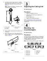
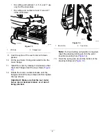
Mount a lift chain to each chain bracket with a
screw, a washer, and a nut, positioning them as
shown in
.
g006540
Figure 8
1.
Lift chain
2.
Chain bracket
3
Adjusting the Cutting Unit
No Parts Required
Procedure
1.
Adjust the bedknife to the reel.
2.
Adjust the rear roller for your height-of-cut
requirements.
3.
Set the height of cut.
4.
Adjust the rear shield if necessary.
Refer to
Adjusting the Cutting Unit (page 10)
for complete instructions for performing these
adjustments
4
Mounting the
Counterweights
No Parts Required
Procedure
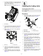
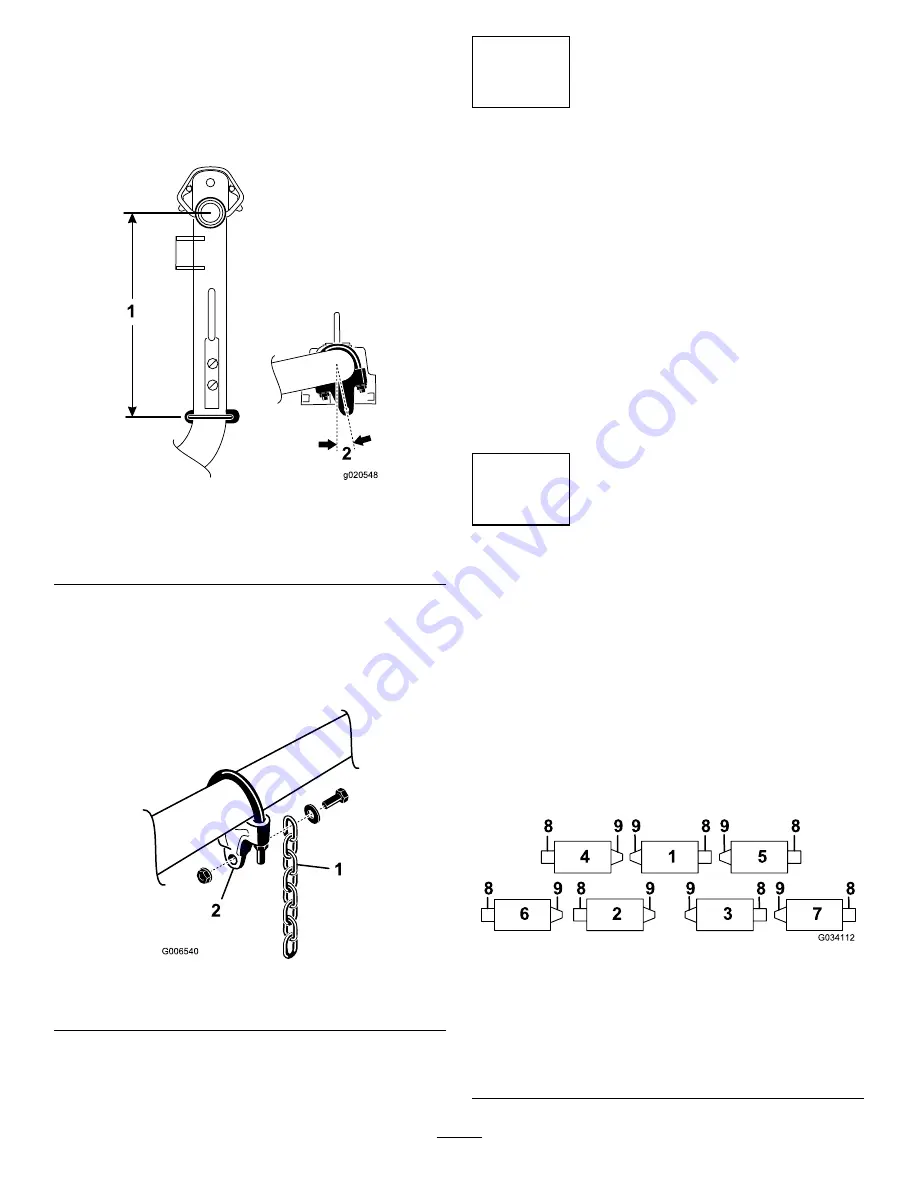
All cutting units are shipped with the counterweight
mounted to the left end of the cutting unit. Use the
following diagram to determine the position of the
counterweights and reel motors.
Note:
Some traction units have only 5 cutting units.
g034112
Figure 9
1.
Cutting unit 1
6.
Cutting unit 6
2.
Cutting unit 2
7.
Cutting unit 7
3.
Cutting unit 3
8.
Reel motor
4.
Cutting unit 4
9.
Weight
5.
Cutting unit 5
7
Содержание 03698
Страница 25: ...Notes ...


