


g305020
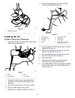
Figure 3
1.
Bolt (M10)
3.
Flange nut (M10)
2.
Slope sensor mount
4.
Install the wire harness connector labeled P02
to the slope sensor (
g307124
Figure 4
1.
Coil the wire harness in
this location.
3.
Wire harness connector
(P02)
2.
Wire harness
5.
Route the wire harness towards the control
panel (
) and ensure that it is secured
and away from moving parts or pinch points.
6.
Coil any additional amount of wire harness to
the left of the control panel (
).
7.
Remove the plug and install the LED light in the
control panel as shown in
.
g307377
Figure 5
1.
LED light
8.
Connect the remaining wire-harness connectors
as follows:
•
Wire harness connector labeled P01:
Connect to one of the 6-pin sealed
connectors located on the main harness
below the control panel.
•
Wire harness connector labeled P08:
Connect to the LED light.
•
Wire harness connector labeled P09:
Connect to the alarm and position the alarm
under the control panel.
Note:
Ensure that the alarm does not
obstruct any controls.
9.
Secure the operator’s platform; refer to your
machine
Operator’s Manual
.
10.
Install the slope-sensor decal adjacent to
the machine-stability decal on the operator’s
platform (
).
3


