


Installation
1
Preparing the Machine
No Parts Required
Procedure
1.
Park the machine on a level surface.
2.
Engage the parking brake.
3.
Lower the cutting unit(s).
4.
Shut off the machine and remove the key.
2
Installing the Kit
Parts needed for this procedure:
1
Slope sensor
1
Slope-sensor mount (LTF/LT/CT only)
1
Slope-sensor mount (T4240 only)
2
Bolt (M6 x 35 mm)
2
Bolt (M6 x 25 mm—LTF/LT/CT only)
4
Flange nut (M6)
2
Bolt (M10—T4240 only)
2
Flange nut (M10—T4240 only)
1
LED indicator
1
Alarm
1
Wire harness
6
Cable tie
1
Slope sensor decal
Installing the Kit
T4240 Machines
1.
Release the operator platform; refer to your
machine
Operator’s Manual
.
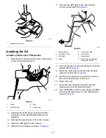
2.
Use 2 bolts (M6 x 35 mm) and 2 flange nuts (M6)
to secure the slope sensor to the slope-sensor
mount.
g304899
Figure 1
1.
Slope sensor mount
3.
Slope sensor
2.
Flange nut (M6)
4.
Bolt (M6 x 35 mm)
3.
Use 2 bolts (M6 x 25 mm) and 2 flange nuts
(M6) to secure the slope sensor mount to the
chassis (
Note:
shows the location of the
chassis with the operator’s platform in the
secured position. The chassis mounting position
is under the operator’s platform.
g307378
Figure 2
2


