54
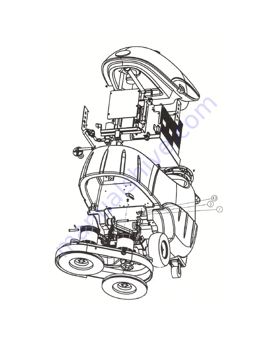
MAIN ASSEMBLY – EXPLODED VIEW “D”
(Ref. Drawing #99430)
https://harrissupplyind.com - To Order Parts Call 608-268-8080
Страница 1: ...ubber Catalog No 99430 Form No L9430C 7 03 2003 Tornado Industries All rights reserved TORNADO INDUSTRIES 7401 W LAWRENCE AVENUE CHICAGO IL 60706 708 867 5100 FAX 708 867 6968 www tornadovac com h t t...
Страница 2: ...2 NOTES h t t p s h a r r i s s u p p l y i n d c o m T o O r d e r P a r t s C a l l 6 0 8 2 6 8 8 0 8 0...
Страница 3: ...ied here For full details contact your Authorized Tornado Distributor Service Center or the Tornado Technical Service Department 1 Year Warranty on batteries one full year not pro rated Effective Janu...
Страница 4: ...CEMENT 21 TROUBLESHOOTING INSTRUCTIONS COMMON ISSUES 22 TROUBLESHOOTING CHART 24 LCD DISPLAY DIAGNOSTIC ERROR CODES 26 PREVENTATIVE MAINTENANCE CHECKLIST 28 ILLUSTRATED PARTS LISTS SOLUTION TANK 29 RE...
Страница 5: ...s free automatic operation off to conserve battery power when double scrubbing and constant on for use with the optional hand tool accessory set The new FK 3000 automatic scrubber was designed and bui...
Страница 6: ...ettes matches or hot ashes Do not pick up flammable or combustible liquids such as gasoline or petroleum solvents or use machine where they may be present When using the charger supplied with this mac...
Страница 7: ...accordance with all local codes and ordinances WARNING Improper connection of the equipment grounding conductor can result in electric shock Check with a qualified electrician or service person if you...
Страница 8: ...Display See page 9 for display capabilities 4 Brush Position Switch 5 Solution Flow Rate Knob 6 Display Mode Button Rear Controls 7 Solution Filler Plug 8 Solution Level Sight Tube 9 Squeegee Control...
Страница 9: ...three unique screens Each screen displays a different set of icons and numerical readouts to give you useful information about your machine s operating status For particulars on diagnostic fault code...
Страница 10: ...10 h t t p s h a r r i s s u p p l y i n d c o m T o O r d e r P a r t s C a l l 6 0 8 2 6 8 8 0 8 0...
Страница 11: ...y 4 To ensure that both the ends and the center of the Squeegee Blades are evenly loaded loosen the Rocker Adjustment Knobs Lower the Squeegee Assembly to the floor by pulling the Squeegee Control Lev...
Страница 12: ...usted the Brush Housing Skirt prevents the rotating brushes from flinging solution off to the sides where the Squeegee may not be able to reach Power the Brush Housing down so that the Brushes or Pads...
Страница 13: ...3000 notice that the charging connector is underneath the Cover Recovery Tank This is a safety feature to ensure that the Cover is open to freely vent battery gases during charging As the Recovery Tan...
Страница 14: ...ralize with sodium carbonate or bicarbonate baking soda Battery Care Batteries must be checked daily The water level must be maintained at least 1 4 above top of cell plates in each battery 1 Raise to...
Страница 15: ...ive plastic terminal covers after battery maintenance Battery Removal Should batteries need to be removed for any reason use two people to perform these tasks 1 Completely drain the Recovery Tank 2 Di...
Страница 16: ...electrical receptacle The red CHARGER ON light will automatically come on along with the INCOMPLETE light meaning batteries are being charged 3 The charger will automatically turn off when the batteri...
Страница 17: ...ere burn H Never charge a frozen battery Charging a frozen battery may result in explosion I Always disconnect the AC supply cord from its outlet and the DC connector from the battery before attemptin...
Страница 18: ...om the Rocker Disconnect the vacuum hose loosen both Squeegee Locking Knobs and slide the Squeegee out 2 Unscrew both Star Knobs at either end of the Squeegee and remove the Rollers 3 Pull off the pla...
Страница 19: ...are worn 4 Clean squeegee blades with a damp cloth And slide them into place The rear Blade is longer than the front and overlaps it evenly on each end 5 Replace the plastic end components and remoun...
Страница 20: ...so be contacting evenly across its length If readjustment is needed loosen the Rocker Adjustment Knobs Rotate the Squeegee Assembly Correct adjustment is made when both Squeegee Blades rest evenly on...
Страница 21: ...es The Recovery Tank is depressurized by the Vacuum Motor and pulls spent solution and debris from the Squeegee into its interior A stand pipe prevents water intake into the Vac Motor and a Float Sens...
Страница 22: ...onto its hook NOTE Flush and clean both tanks after each use and allow to air dry to eliminate odors and corrosion of vacuum motor Vacuum Motor To service vacuum motor which is mounted to the undersi...
Страница 23: ...more often due to commutator wear Always permanently record any brush inspections and replacements you make Don t attempt to use the Motor Fault Error feature of the LCD Display as a signal that moto...
Страница 24: ...n place on the end of the Recovery Tank drain hose 5 Check to see that the Recovery Tank Cover disk is seated properly on its gasket 6 Check to see that the liquid shutoff unit is properly seated at r...
Страница 25: ...mber light All cells are OK but the total battery capacity is reduced This usually indicates that the batteries are aging C Red light The battery capacity is low and the entire charger battery system...
Страница 26: ...Consult authorized Tornado Service Center Unit moves forward but not reverse Faulty component or circuitry Consult authorized Tornado Service Center Unit does not move forward or reverse Batteries dis...
Страница 27: ...sting brush pressure increasing solution or changing to a less aggressive pad Wait several minutes reset circuit breaker then resume operation Brushes in up position Lower brushes Faulty brush motor o...
Страница 28: ...eference error 0814 Throttle Low reference error 0815 Throttle High reference error ISO error 0816 Throttle Low reference error ISO error 0817 Throttle Both LCD module and TRIO unit have throttles 081...
Страница 29: ...rip latch 12 error 360C Test trip latch 13 360D Test trip latch 14 360E 700x Freewheel Codes Startup with freewheel activated 7000 Freewheel activated in drive mode 7001 750x LCD Comms codes LCD Modul...
Страница 30: ...h a light oil Adjust the brush pressure mercury switch if needed Check for wear or damage of brushes pads and squeegee blades replace if necessary Clean all battery terminals with baking soda and wate...
Страница 31: ...31 SOLUTION TANK EXPLODED VIEW A Ref Drawing 31504 h t t p s h a r r i s s u p p l y i n d c o m T o O r d e r P a r t s C a l l 6 0 8 2 6 8 8 0 8 0...
Страница 32: ...32 SOLUTION TANK EXPLODED VIEW B Ref Drawing 31504 h t t p s h a r r i s s u p p l y i n d c o m T o O r d e r P a r t s C a l l 6 0 8 2 6 8 8 0 8 0...
Страница 33: ...E 11 2 19513 NUT HEX LOCK NYLON INSERT 5 16 18 12 1 19544 SOLUTION TANK 13 1 19596 BRACKET GAS SPRING MOUNTING 14 1 19724 GAS SPRING 15 1 19948 HANGER DRAIN HOSE 16 1 30533 HOSE W BELLOWS 17 2 30623 S...
Страница 34: ...34 RECOVERY TANK EXPLODED VIEW Ref Drawing 31503 h t t p s h a r r i s s u p p l y i n d c o m T o O r d e r P a r t s C a l l 6 0 8 2 6 8 8 0 8 0...
Страница 35: ...T VACUUM MOTOR 10 1 19270 FITTING RECOVERY HOSE 11 1 19543 RECOVERY TANK 12 1 19596 BRACKET GAS SPRING MOUNTING 13 1 19708 FLOAT SWITCH 14 1 19930 VACUUM MOTOR 15 1 19973 ASSEMBLY VAC INTAKE 16 1 3050...
Страница 36: ...36 SQUEEGEE ASSEMBLY EXPLODED VIEW Ref drawing K47770560 h t t p s h a r r i s s u p p l y i n d c o m T o O r d e r P a r t s C a l l 6 0 8 2 6 8 8 0 8 0...
Страница 37: ...K53080570 HEX STUD DOUBLE SIDED THREAD 10 2 K54012440 INSERT PLATE 11 2 K54012500 INSERT PLATE 12 2 K55150960 WHEEL 4 DIA BLACK 13 1 K62732150 SQUEEGEE BLADE SET 14 2 K63211330 STAR HANDLE 15 2 K63211...
Страница 38: ...38 SQUEEGEE MOUNT ASSEMBLY EXPLODED VIEW Ref Drawing 32031 h t t p s h a r r i s s u p p l y i n d c o m T o O r d e r P a r t s C a l l 6 0 8 2 6 8 8 0 8 0...
Страница 39: ...19 1 19599 HANDLE SQUEEGEE LIFT 20 1 19600 MOUNTING BRACKET LIFT HANDLE 21 4 30647 SCREW HEX HEAD FLANGED 3 8 16 X 1 2 22 1 31938 PIVOT LIFT 23 1 31947 U BOLT 3 8 16 24 1 32016 MAIN SUPPORT BRACKET 2...
Страница 40: ...40 BRUSH DRIVE ASSEMBLY EXPLODED VIEW Ref Drawing 31501 h t t p s h a r r i s s u p p l y i n d c o m T o O r d e r P a r t s C a l l 6 0 8 2 6 8 8 0 8 0...
Страница 41: ...41 BRUSH DRIVE ASSEMBLY PARTS LIST Ref Drawing 31501 h t t p s h a r r i s s u p p l y i n d c o m T o O r d e r P a r t s C a l l 6 0 8 2 6 8 8 0 8 0...
Страница 42: ...42 TRANSAXLE ASSEMBLY EXPLODED VIEW Ref Drawing 19686 h t t p s h a r r i s s u p p l y i n d c o m T o O r d e r P a r t s C a l l 6 0 8 2 6 8 8 0 8 0...
Страница 43: ...43 TRANSAXLE ASSEMBLY PARTS LIST Ref Drawing 19686 h t t p s h a r r i s s u p p l y i n d c o m T o O r d e r P a r t s C a l l 6 0 8 2 6 8 8 0 8 0...
Страница 44: ...44 CONTROL BOX SOLUTION PUMP MODULE EXPLODED VIEW Ref Drawing 31469 h t t p s h a r r i s s u p p l y i n d c o m T o O r d e r P a r t s C a l l 6 0 8 2 6 8 8 0 8 0...
Страница 45: ...45 CONTROL BOX SOLUTION PUMP MODULE PARTS LIST Ref Drawing 31469 h t t p s h a r r i s s u p p l y i n d c o m T o O r d e r P a r t s C a l l 6 0 8 2 6 8 8 0 8 0...
Страница 46: ...46 ACTUATOR ASSEMBLY EXPLODED VIEW PARTS LIST Ref Drawing 31386 h t t p s h a r r i s s u p p l y i n d c o m T o O r d e r P a r t s C a l l 6 0 8 2 6 8 8 0 8 0...
Страница 47: ...47 CONTROL PANEL EXPLODED VIEW Ref Drawing 31474 h t t p s h a r r i s s u p p l y i n d c o m T o O r d e r P a r t s C a l l 6 0 8 2 6 8 8 0 8 0...
Страница 48: ...48 CONTROL PANEL PARTS LIST Ref Drawing 31474 h t t p s h a r r i s s u p p l y i n d c o m T o O r d e r P a r t s C a l l 6 0 8 2 6 8 8 0 8 0...
Страница 49: ...49 TRIGGER ASSEMBLY EXPLODED VIEW Ref Drawing 31500 h t t p s h a r r i s s u p p l y i n d c o m T o O r d e r P a r t s C a l l 6 0 8 2 6 8 8 0 8 0...
Страница 50: ...50 TRIGGER ASSEMBLY PARTS LIST Ref Drawing 31500 h t t p s h a r r i s s u p p l y i n d c o m T o O r d e r P a r t s C a l l 6 0 8 2 6 8 8 0 8 0...
Страница 51: ...51 MAIN ASSEMBLY EXPLODED VIEW A Ref Drawing 99430 h t t p s h a r r i s s u p p l y i n d c o m T o O r d e r P a r t s C a l l 6 0 8 2 6 8 8 0 8 0...
Страница 52: ...52 MAIN ASSEMBLY EXPLODED VIEW B Ref Drawing 99430 h t t p s h a r r i s s u p p l y i n d c o m T o O r d e r P a r t s C a l l 6 0 8 2 6 8 8 0 8 0...
Страница 53: ...53 MAIN ASSEMBLY EXPLODED VIEW C Ref Drawing 99430 h t t p s h a r r i s s u p p l y i n d c o m T o O r d e r P a r t s C a l l 6 0 8 2 6 8 8 0 8 0...
Страница 54: ...54 MAIN ASSEMBLY EXPLODED VIEW D Ref Drawing 99430 h t t p s h a r r i s s u p p l y i n d c o m T o O r d e r P a r t s C a l l 6 0 8 2 6 8 8 0 8 0...
Страница 55: ...55 MAIN ASSEMBLY PARTS LIST Ref Drawing 99430 h t t p s h a r r i s s u p p l y i n d c o m T o O r d e r P a r t s C a l l 6 0 8 2 6 8 8 0 8 0...
Страница 56: ...56 WIRING DIAGRAM Sheet 1 of 2 Ref Drawing 31417 h t t p s h a r r i s s u p p l y i n d c o m T o O r d e r P a r t s C a l l 6 0 8 2 6 8 8 0 8 0...
Страница 57: ...57 WIRING DIAGRAM Sheet 2 of 2 Ref Drawing 31417 h t t p s h a r r i s s u p p l y i n d c o m T o O r d e r P a r t s C a l l 6 0 8 2 6 8 8 0 8 0...
Страница 58: ...58 WIRING HARNESS CONTROL FUNCTION Sheet 1 of 2 Ref Drawing 31418 h t t p s h a r r i s s u p p l y i n d c o m T o O r d e r P a r t s C a l l 6 0 8 2 6 8 8 0 8 0...
Страница 59: ...59 WIRING HARNESS CONTROL FUNCTION Sheet 2 of 2 Ref Drawing 31418 h t t p s h a r r i s s u p p l y i n d c o m T o O r d e r P a r t s C a l l 6 0 8 2 6 8 8 0 8 0...
Страница 60: ...60 WIRING HARNESS POWER FUNCTION Sheet 1 of 2 Ref Drawing 31419 h t t p s h a r r i s s u p p l y i n d c o m T o O r d e r P a r t s C a l l 6 0 8 2 6 8 8 0 8 0...
Страница 61: ...61 WIRING HARNESS POWER FUNCTION Sheet 2 of 2 Ref Drawing 31419 h t t p s h a r r i s s u p p l y i n d c o m T o O r d e r P a r t s C a l l 6 0 8 2 6 8 8 0 8 0...
Страница 62: ...Pad Holder 10 30543 Oil Resistant Linatex Front Squeegee Blade 2 30544 Oil Resistant Linatex Rear Squeegee Blade 2 Optional Items 99172 16 Firm Poly Scrub Brush 2 required 8 99173 16 Grit Brush 2 requ...