P: 1-866-829-4411
E: [email protected]
F: 1-519-539-9191
USA: Tork Winch USA LLC
5020 Hazel Jones Road
Bossier City, LA | 71111
CANADA: Tork Winch
125 Bysham Park Drive
Woodstock, ON | N4T 1P1
TW 2000 BASKETBALL BACKSTOP WINCH
GYMNASIUM
Installation Instructions Continued >
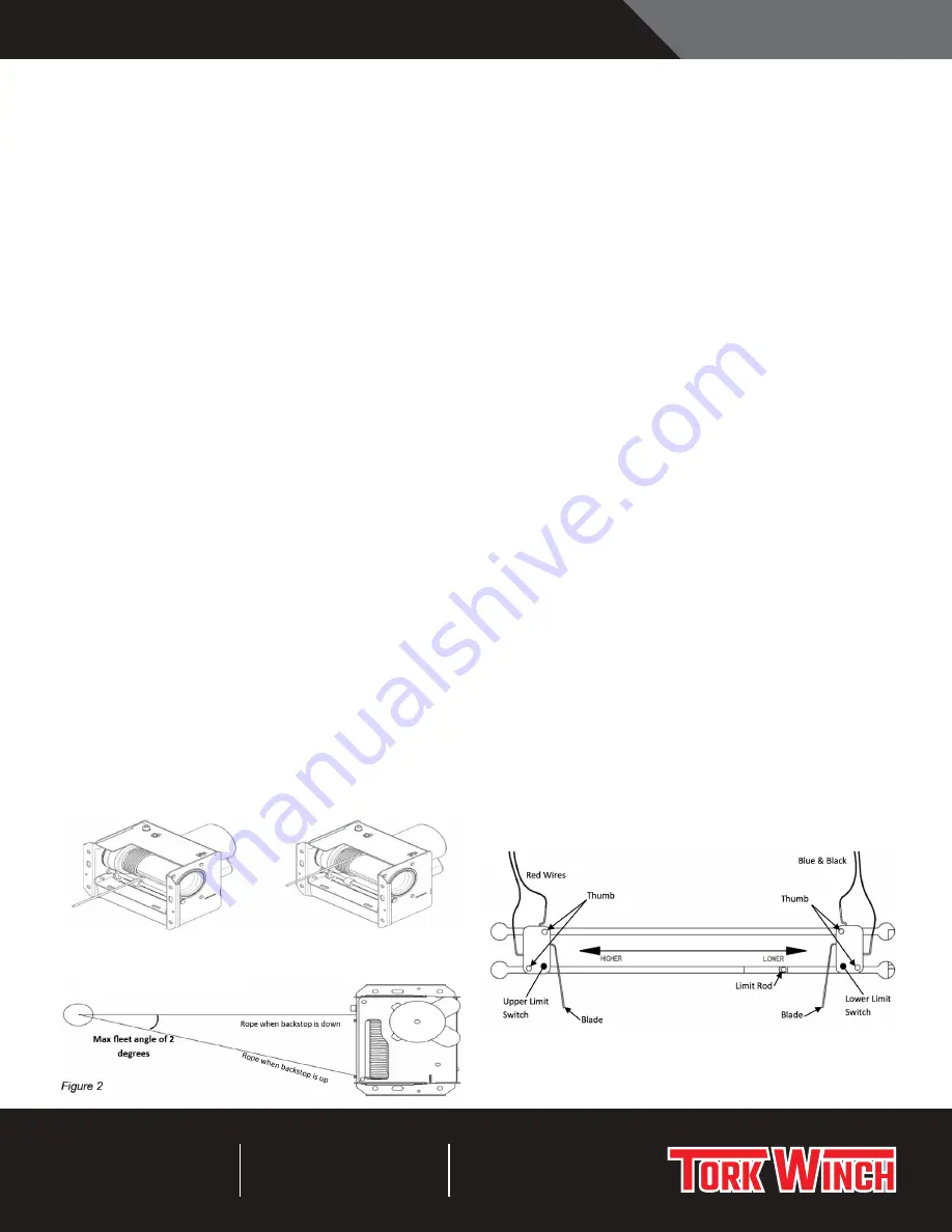
WIRE ROPE INSTALLATION (SEE FIG. 2)
The winch is designed for standard 1/4” diameter 7 x 19 aircraft
cable. The rope passes through a hole in the drum and is
prevented from pulling out by doubling the end back on itself
and securing with a standard rope clamp.
1. Manually turn the motor shaft with a ½” wrench to bring
the wire rope mounting hole in winch drum to an easily
accessible position.
2. Pass the wire rope from outside the winch in through the
rope port and then through the hole in the drum into the
center of the hollow drum. Pass enough cable through to
allow pulling of the free end.
3. Double the cable end back on itself and install the supplied
cable clamp. Tighten clamp nuts using a ½” wrench –
progressively alternating sides until clamp is fully secured.
4. Pull the rope back through the hole to bring the clamp back
tight to the hole inside the drum.
5. Running the winch in the “up” direction will begin winding
the wire rope onto the drum. Run the winch so that a
total of 3 revolutions of cable wound on the drum. These
revolutions are considered “dead wraps”- this length of
wire rope must remain on the drum at all times.
(Use extreme caution and keep hands and clothing away
from moving parts).
6. A) The cable can now be reeved over directional pulleys
and down to the mast as per the backstop manufacturer’s
recommendations. At the starting side of the drum, the
rope must exit perpendicular to the winch (0° fleet angle)
as it travels to the head pulley (see Fig. 2)
B) If no head pulley is installed in the system and the winch
is used as a direct pull; the fleet angle MUST be as close to
0° as possible when the backstop is in the fully raised position.
PLEASE NOTE:
Put only three “dead wraps” on the drum at the start of the lift.
Excessive dead wraps use space on the grooved drum-forcing
the rope onto a second layer when it is not needed.
LIMIT SWITCH ADJUSTMENT
1. Run the winch in the “up” direction to raise the backstop to
the desired (fully raised) position and stop it in this position.
Turn off the power to the winch at the breaker and remove
the electrical compartment cover. (2 hex screws)
2. Loosen the two thumb nuts holding the upper limit switch.
3. Slide the upper limit switch across until the blade contacts
the limit rod, then slide it a little further until an audible
click is heard as the switch opens. Tighten the thumb nuts.
Do not over tighten thumb nuts as this may crack the
limit switches.
The top limit is now set.
4. Temporarily reinstall the cover and run the backstop down
to the desired lower stop position. Set the lower limit
switch the same way.
5. Run the backstop up and down again to ensure that the
limit positions are set correctly. Note: The wire rope should
not be under a slack condition when the backstop is in the
lower position.
6. Make a final check to make sure that all fasteners are
tight and the rope is tracking properly in the drum grooves
before putting the winch into use.
PLEASE NOTE:
One upper and one lower travel limit switch is provided. Proper
adjustment is simple and quick with the following procedure.
Always shut power off from the winch when working inside the
electrical compartment. The cover has been designed for quick
removal to simplify limit switch adjustment.
INSTALLATION INSTRUCTIONS
Rope must be wound on the drum
in this direction.
Rope wound in wrong direction.
Front pulley should be aligned with the motor side of the winch drum.


