


Apalis Carrier Board Design Guide
Toradex AG l Altsagenstrasse 5 l 6048 Horw l Switzerland l +41 41 500 48 00 l
l
Page | 55
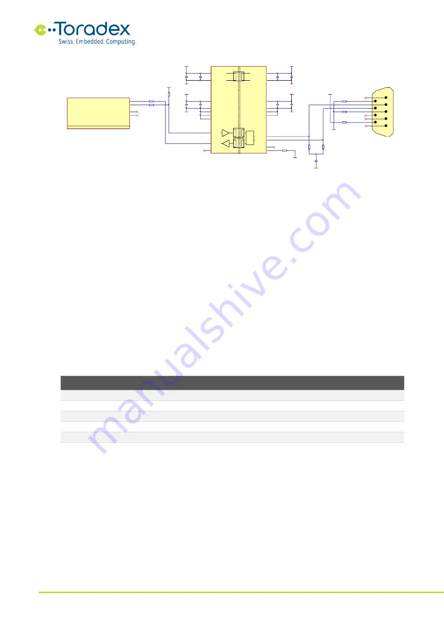
Figure 49: CAN Reference Schematic
2.17.3 Unused CAN Interface Signal Termination
According to the Apalis standard, the CAN interface signals do not need to be GPIO capable. It
depends on the module whether the CAN interface signal pins can be used for other purposes if
the CAN interface is not in use. Some Apalis modules provide the CAN interface by using a
dedicated controller. It is recommended to tie the CAN RX signals to ground or 3.3V if the interface
is not used. This can help in reducing the power consumption of modules with stand-alone CAN
controller.
2.18 PWM
The Apalis module form factor defines five pulse width modulator (PWM) outputs - four general
purpose outputs and one dedicated for the backlight of the display. Since not all SoCs provide up
to five PWM channels, there might be some shared channels which cannot be used concurrently.
Please read the relevant datasheet of the module carefully. The maximum output frequency and
the available duty cycle steps can also vary between the different Apalis modules.
2.18.1 PWM Signals
Apalis
Pin
Apalis
Signal Name
I/O
Type
Power
Rail
Description
2
PWM1
O
CMOS
3.3V
General purpose PWM output
4
PWM2
O
CMOS
3.3V
General purpose PWM output
6
PWM3
O
CMOS
3.3V
General purpose PWM output
8
PWM4
O
CMOS
3.3V
General purpose PWM output
239
BKL1_PWM
O
CMOS
3.3V
Dedicated PWM output for the LCD display backlight
Table 30: PWM Signals
2.18.2 Reference Schematics
The PWM output signals can be used to drive motors, LEDs, robotic servos, fans, etc. It is possible
to get an analogue signal with a simple low pass filter.
CAN1_TX
CAN1_RX
100nF
16V
C105
100nF
16V
C106
CAN1_L
CAN1_H
CAN1_GND_ISO
GND
CAN1_5V_ISO
0R
R106
MM70-314-310B1
CAN1_RX
12
Apalis - CAN
17 of 25
CAN1_TX
14
CAN2_RX
16
CAN2_TX
18
X1Q
3.3V_SW
3.3V_SW
22R
RA4C
22R
RA4D
CAN1_GND_ISO
5V_SW
ADM3053BRWZ
VCC
8
VIO
6
VISOOUT
12
VISOIN
19
VREF
14
RXD
4
TXD
5
CANL
15
CANH
17
RS
18
GND1_2
3
GND1_3
9
GND1_4
7
GND1_5
10
GND1_1
1
GND2_2
11
GND2_3
16
GND2_4
13
GND2_1
20
NC
2
CAN
IC10
10uF
10V
C104
10uF
10V
C107
100nF
16V
C109
GND
10nF
25V
C108
100nF
16V
C111
10nF
25V
C110
CAN1_5V_ISO
CAN1_GND_ISO
R105
10K
56R
R107
56R
R108
47nF
16V
C112
CAN1_GND_ISO
CAN1_PGND
R99
100R
CAN1_PW
U1
U2
U3
U4
U5
U6
U7
U8
U9
178-009-613R571
X32A
CAN Connector
CAN1_5V_ISO
CAN1_GND_ISO
0R
R100
0R
R101
NA
NA


