POWERED FLOW-THROUGH HUMIDIFIER
68-3074—01
6
CHECKOUT PROCEDURE
After winter startup or servicing, use the following steps to
check the humidifier operation.
1.
Turn on the humidifier power and water supply.
2.
Turn the humidity control to its highest setting and set the
thermostat to 10 °F (12 °C) above the room temperature.
3.
Observe that water is flowing out of the drain hose.
NOTE: The furnace blower must be operating for the humidi-
fier to work.
4.
Reset the thermostat and humidity control to a comfort-
able setting for automatic operation.
TROUBLESHOOTING
Refer to Table 2 for troubleshooting procedures.
REPLACEMENT PARTS
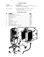
Refer to Fig. 10 and Table 3 when ordering replacement parts.
Table 2. Troubleshooting Procedures.
Problem
What To Look For
What To Do
Low humidity
Furnace blower not operating.
• Reset circuit breaker or check for blown fuse.
• Check that the furnace power is on.
• Check all external wiring connections.
• Check the humidity control setting.
• Call a professional heating contractor.
Rapid air changes. Drafts (cold air is dry
and is an added load to the humidifier).
• Keep doors and windows closed.
• Close fireplace damper when not in use.
• Keep exhaust fan running time to a minimum.
• Seal around doors and windows.
High humidity
Condensation on walls.
• Turn off humidity control and water until condensation is
completely evaporated.
Heavy condensation on windows.
• Turn humidity control down low enough to eliminate
condensation caused by moisture from bathing, mopping,
cooking, etc. If moisture persists, more ventilation is needed.
Table 3. List of Replacement Parts.
1
Water Distribution Tray
32001630-001
2
Solenoid Valve Assembly (Includes water feed tube)
32001876-001
3
Antimicrobial Humidifier Pad
HC26E1004
4
PWB Assembly
32001676-001
5
Bag Assembly, Saddle Valve
32001616-001
6
Convertible Humidity Control
H8908ASPST
Not Shown Hardware Kit for Solenoid Assembly (same as Solenoid Valve Assembly without the solenoid valve) 32001752-001


