- 14 -
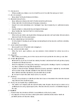
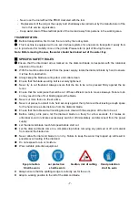
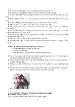
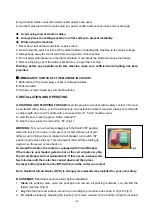
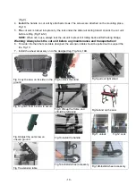
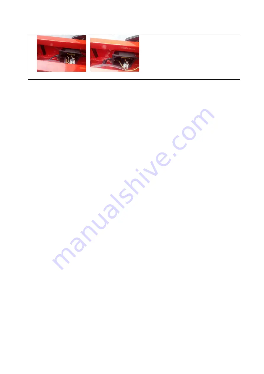
Fig.25D-Loose and replace the pump.
Warning: make sure that you have pulled the Plug from the main socket when you do the
following maintenance.
1. Clean the pump
To clean the pump, remove the intake cover, and then take out of the filter foam
and impeller cover. Use a small brush or stream of water to remove any debris on the foam and the
impeller. (Fig.25A)
Note: Please clean the pump immediately after you stop use
.
Otherwise the dry debris could
stick the filter foam and the impeller, which will cause you to replace the filter foam or the
pump.
2. Replace the filter foam
To replace the filter foam, remove the intake cover, then take out of the
filter foam and put into a new one.
3. Replace the pump
After replacing new filter foam, if the pump still does not work, you have to
replace problem pump with a new one, only use the pump recommended by the manufacturer of
the machine. The changing procedures are as follows:
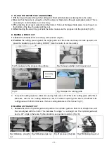
3.1 Loosen the bolt of the pump connecting box located inside the main frame and remove the cover
(Fig.25B).
3.2 Loosen the bolt of the pump cable lock and take the pump plug out of connecting box (Fig.25C,
25D).
3.3 Take out the pump and replace a new one, install the new pump by reversing above procedures
Note: Only an authorized person should perform other repairs!
B. ALIGNMENT MAINTENANCE
This saw motor or bridge does not need to be squared up or aligned, since the bridge does not allow
the saw motor to move. When it appears that the saw is out of alignment, it is the rip fence that needs to
be squared up.
Tools needed:
24” Framing Square, Phillips Screw Driver and 1/4
″
Nut Driver or Pliers
The following steps should be used to align the rip fence for the Bridge Saw:
1. Pull the power unit towards you and lock in place with the transport lever.
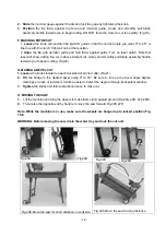
2. Once the power unit is secured, place the Framing square firmly against the blade on the
left side of the cutting surface. The square must be flush with the blade.
(See Fig.26A)
.
3. Slide the square into the rip fence, making sure the square stays firmly against the blade. Look for
a gap between the square and the rip fence. If there is a gap, adjustments will be necessary.
(See
Fig.26B)
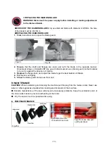
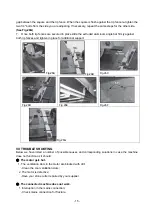
4. To adjust the gap, first remove the Angle cutting guide. This will expose two screws in the
aluminum track. Loosen both screws in the extruded aluminum bar.
(See Fig.26C&D)
5. From underneath the saw, directly below the rip fence, there are two 1/4
″
bolts located under the
left rip fence and 2 bolts under the right rip fence. Loosen both bolts for the rip fence that you are
adjusting.
(See Fig.26E&F)
6. Once the screws are loose, easily slide the rip fence above, allowing you to close the


