background image


order to maintain proper stability. 

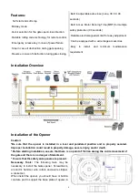
The installation proceeds are as follows: 
1. 

Dig a hole for a concrete pad which should 

be approximately 40 x 24 x 30cm (15.7”x 9.4”x 
11.8”). It may protrude 10 cm (4”) above ground 
and 20 cm (7.9”) in depth underground. 
Increase the pad height if necessary to protect 
the system from flooding, heavy snow etc.   

2.

  Prepare one or more conduits for the 

electrical cables before pour concrete. 
Remember that cable conduits have to pass 
through the hole in opener base. 

3. 

Pour concrete and before it starts to harden, 

check that it is parallel to the gate leaf and 
perfectly level. 

4.

 Make sure the position of Expansion Tubes 

was placed according to the position of 
mounting holes on the opener base. 

5. 

Mount the opener to the concrete Pad. It's only temporary installation. Further adjustment will be 

required when install the rack.   
 

Manual Operation   

You can open the gate by manual when power failure. And the opener should be put in the manual 
(emergency release) position before fitting the rack, installing the opener and limit switch. The process is as 
follows: 
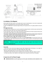
Insert the Release Key and turn it in clockwise 90°, then pull the release handle in clockwise 90° to 
disengage the clutch between the gear shaft and motor. Now the opener is in the manual operation. 


Fit the Plastic Rack Reinforced with Steel 

1. Start with gate in closed position 
2. Prepare the plastic rack (you can order extra rack from dealer if necessary). 
3. Put one end of rack section on the gear of opener as a temporary support. 
Make rack level and mark the rack’s mounting holes 

(four holes for light duty or six holes for heavy duty)


on the gate. 
4. Fit the rack by self-threading screws. This kind of plastic rack is quieter and allows height adjustments to 
be made even after it has been fixed. Please keep 1.0mm space between the rack and the gear to avoid the 
weight of the gate effect on the opener. 

Содержание DKR500

Страница 1: ...om VER 21b C030566 DKR500 S Y T Please read and follow all warnings precautions and instructions before installation and use Never connect the solar panel to the control board directly to charge the b...

Страница 2: ...azon co uk Amazon de Other Please Specify Order Product Model Purchase Date Full Name Phone Email Address VERY IMPORTANT Street Address Apartment Unit City State Province Zip Code Country Region Appro...

Страница 3: ...rts 5 Technical Specifications Features 5 Installation Overview 6 Installation of the Opener 6 Manual Operation 7 Fit the Plastic Rack Reinforced with Steel 7 Installation of the Magnets 8 Connection...

Страница 4: ...ntation could damage the product and be dangerous The factory declines all responsibility for any consequences resulting from improper use of the product or use which is different from that expected a...

Страница 5: ...gate opener check that all moving part as well as the sliding gate is in good mechanical condition correctly balanced and opens and closes properly Save these instructions for future use Preparation f...

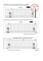
Страница 6: ...3 In sake of safety a positive stop must be mounted on the two end of ground track...

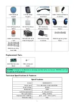
Страница 7: ...ded in some models refers to the actual package Optional Accessories Parts List Available at TOPENS Store M12 Remote Control ERM12 External Receiver TC186 R WiFi Smartphone Remote Control with Camera...

Страница 8: ...Heavy Duty Gear Rack RNH4 Heavy Duty Gear Rack Replacement Parts DKPYMJ1B Control Board PYMJ CKG Limit Switch Technical Specifications Features Specifications Model DKR500 S Y T Power input 110 120V 6...

Страница 9: ...install and minimum maintenance requirement Installation Overview Installation of the Opener Caution Be sure that the opener is installed in a level and paralleled position and is properly secured Imp...

Страница 10: ...the rack Manual Operation You can open the gate by manual when power failure And the opener should be put in the manual emergency release position before fitting the rack installing the opener and lim...

Страница 11: ...side from the view inside of property Ensure magnet center to align with the marked line above The magnets should be 25 30mm 1 1 2 away from the Limit Switch Box If it is too near or too far the swit...

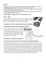
Страница 12: ...is situation you can connect the AC electricity following the Power Mode 1 and the batteries to the BAT terminal of the control board directly as the below wiring diagram Power Mode 3 Only use the bat...

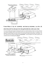
Страница 13: ...ong time maybe 4 5 days one time then you can charge the batteries with the AC electricity and the solar panel at the same time The capacity of the batteries should be at least 7Ah and the power of th...

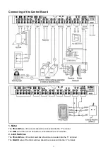
Страница 14: ...uld be connected into the 1 terminal The RED wire of the motor should be connected into the 2 terminal 2 Limit Switches The YELLOW wire of the limit switches should be connected into the 3 terminal Th...

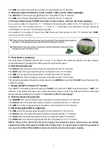
Страница 15: ...N wire of the exit wand should be connected into the 19 terminal The sensitivity adjustment board should be wired to the GREEN wire and the YELLOW wire of the wand No matter the polarity 7 Battery ONL...

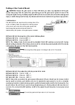
Страница 16: ...NOTE The midway mode function would be disabled if both DIP switches are turned off Factory default setting is disabled The midway mode could be activated by pressing button B of the remote control w...

Страница 17: ...imum Test the Reversing Sensitivity For the sake of safety it is very important to test the reversing sensitivity as soon as the control board set is finished The reversing sensitivity adjustment is i...

Страница 18: ...Universal External Receiver is also compatible with other brand swing gate opener sliding gate opener and garage door opener How to Use the Remote to Operate Your Gate Opener Each remote has four butt...

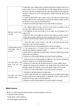
Страница 19: ...pener does not run Power LED is OFF 1 Make sure that the power cord is properly plugged into the mains outlet 2 Check if the output voltage of the transformer is 24VAC If the voltage measures 0 the tr...

Страница 20: ...k the control board Replace the control board if necessary The gate starts but it is immediately stop or reverse 1 Check the HALL sensor board in the side of the gear box has been connected to the con...

Страница 21: ...earthed and correctly terminated Always check the Stop Reverse in case of obstruction function when performing any maintenance If this function can t be made operable remove this opener from service u...

Страница 22: ...e any need to contact us the info below will help you get in touch TOPENS Website www topens com Contact Us E mail support topens com Kindly include your Product Model Purchasing Date Site Order and y...

Отзывы: