103
19. SURFACE AREA CALCULATION
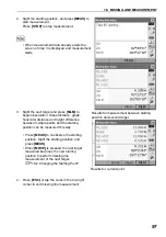
5. Press
[CALC]
to display the calculated area.
6. Press
[OK]
to return to <Area/key in coord.>.
Press
{ESC}
or tap the cross in the top-right
corner to quit area calculation.
Страница 1: ...SURVEYING INSTRUMENTS Class 3R Laser Product OPERATOR S MANUAL FX series FX 101 FX 102 FX 103 FX 105 FX 107 Functional X ellence Station...
Страница 2: ...Li ion S Li ion This is the mark of the Japan Surveying Instruments Manufacturers Association...
Страница 3: ...ction to output data to a connected host computer Command operations from a host computer can also be performed For details refer to Communication manual and ask your local dealer The specifications a...
Страница 4: ...g in this manual are of FX 103 with Bluetooth module and display on face 1 only Face 2 display is available as standard or as a factory option depending on the country of purchase Location of softkeys...
Страница 5: ...ak Company Bluetooth is a registered trademark of Bluetooth SIG Inc Windows and Windows CE are registered trademarks of Microsoft Corporation All other company and product names featured in this manua...
Страница 6: ...attery 32 8 SETTING UP THE INSTRUMENT 34 8 1 Centering 34 8 2 Levelling 36 9 POWER ON OFF 38 9 1 Resolving Software Issues 39 9 2 Configuring the Touch Panel 39 10 CONNECTING TO EXTERNAL DEVICES 41 10...
Страница 7: ...7 16 3 Coordinates Setting out Measurement 82 16 4 REM Setting out Measurement 85 17 OFFSET MEASUREMENT 88 17 1 Single distance Offset Measurement 88 17 2 Angle Offset Measurement 91 17 3 Two distance...
Страница 8: ...ion 132 22 4 Reticle 133 22 5 Optical Plummet 135 22 6 Additive Distance Constant 136 22 7 Laser Plummet Option 138 23 POWER SUPPLY SYSTEM 141 24 TARGET SYSTEM 142 25 OPTIONAL ACCESSORIES 144 26 SPECI...
Страница 9: ...printed in or near the symbol I This symbol indicates items which must always be performed Specific details are printed in or near the symbol C Warning D Do not use the unit in areas exposed to high...
Страница 10: ...an those designated An explosion could occur or abnormal heat generated leading to fire D Do not use damaged power cords plugs or loose outlets Fire or electric shock could result D Do not use power c...
Страница 11: ...E Tighten the leg fixing screws securely before carrying the tripod Failure to tighten the screws could lead to the tripod legs extending causing injury C Warning D Do not use within the vicinity of h...
Страница 12: ...t the FX from moisture and dust particles when the connector is not in use Make sure that moisture or dust particles do not come in contact with the terminal or connectors Operating the instrument wit...
Страница 13: ...ry will change with environmental conditions The lens cap and lens hood may become difficult to attach in low temperatures Keep them in a warm place such as a pocket until attached If the unit is carr...
Страница 14: ...ens wipe it with the wiping cloth If the display is dirty carefully wipe it with a soft dry cloth To clean other parts of the instrument or the carrying case lightly moisten a soft cloth in a mild det...
Страница 15: ...ofits due to any natural disaster earthquake storms floods etc fire accident or an act of a third party and or usage under unusual conditions The manufacturer or its representatives assumes no respons...
Страница 16: ...hazardous radiation exposure Follow the safety instructions on the labels attached to the instrument as well as in this manual to ensure safe use of this laser product Never point the laser beam at a...
Страница 17: ...could cause serious injury Only those who have been received training as per the following items shall use this product Read the Operator s manual for usage procedures for this product Hazardous prot...
Страница 18: ...sing ring 13 Optical plummet eyepiece 14 Optical plummet reticle cover 15 Luminance sensor 16 Guide light 17 Objective lens Includes Laser pointer function 18 Handle locking screw 19 Tubular compass s...
Страница 19: ...tribrach dish to this mark Instrument height is input when setting instrument station data and is the height from the measuring point where FX is mounted to this mark Trigger key When the Trigger key...
Страница 20: ...be damaged if struck during operation or while being stored in the carrying case Handle The carrying handle can be removed from the instrument To remove it loosen the handle rocking screw G To remove...
Страница 21: ...distance measurement Do not switch between modes by PRG or not turn OFF the power during displaying the message Executing program mode 4 2 Mode Structure Program mode Star key mode Top menu Observatio...
Страница 22: ...causing communication failure or reduction of transmission speed Although a radio station license is not required for this instrument bear in mind the following points when using Bluetooth technology...
Страница 23: ...Moreover wood glass and plastic containing metal frames plates foil and other heat shielding elements as well as coatings containing metallic powders may adversely affect Bluetooth communication and...
Страница 24: ...message Executing program mode I Switching target type C 20 3 EDM Settings Changes can also be made by tapping the display with the stylus pen C 5 2 Display Functions 5 1 Basic Key Operation Power ON...
Страница 25: ...during numeric input mode Input alphabetic character in the order they are listed in alphabetic input mode Input a decimal point during numeric input mode Input a plus or minus sign during numeric in...
Страница 26: ...mple Entering computer lower case as the name of a new device 1 Tap the input mode icon in the status bar second from bottom until _a is displayed 2 Press 7 three times c is displayed 3 Press 5 three...
Страница 27: ...g Example selecting a reflector type Method 1 1 Select EDM in the first page of Observation mode or EDM in Config mode Configuration mode CI Observation mode screen P 22 2 Move to Reflector using O G...
Страница 28: ...the display or use any sharp implement other than the stylus pen to operate the touch panel Using the stylus The stylus pen can be used to select menus and buttons on the screen and operate the scroll...
Страница 29: ...ap on the status bar Touch panel temporarily de activated is displayed The touch panel cannot be operated while the above message is displayed Press ESC to cancel the message and re activate the touch...
Страница 30: ...SHV and SHVdist tabs An SHVdist tab will be created when one does not exist C 20 1 Observation Conditions C 20 6 Allocating Key Functions 2 Vertical angle The Vertical angle display can be switched b...
Страница 31: ...ration screen I Graphic tab The Graphic tab display can be modified using the softkeys in the second page CNFG In Graphic configuration the user can specify the orientation of the graphic tab display...
Страница 32: ...options resume function will be canceled When power is back ON the instrument will be reset C 9 POWER ON OFF Resume function It is possible to re arrange status bar icons C 20 7 Changing Status Bar I...
Страница 33: ...configuration of prism constant Prism 0mm Sheet 0mm N Prism Target information can be edited recorded in Reflector setting C 20 3 EDM Settings 3 PPM setting Configuration of EDM 4 Laser pointer guide...
Страница 34: ...nection via RS232C cable Connection via Bluetooth wireless technology FX set as Master device blue antenna Connection via Bluetooth wireless technology FX set as Slave device green antenna When Blueto...
Страница 35: ...characters and upper case characters can be switched each time by pressing SHIFT and 1 to 9 together 8 Input panel C 5 4 Inputting Characters using the Input Panel I Star key mode Press star key to e...
Страница 36: ...instrument Free space Free space of disk capacity of the instrument Capacity Disk capacity of the instrument Removable Disk Usede space Usage space of disk capacity of the external disk connected to...
Страница 37: ...oves the cursor to the next text box CAP Alternates between upper and lower case alphabetic characters and numbers symbols Shift Alternates between upper and lower case alphabetic characters and numbe...
Страница 38: ...e hatch by sliding its button 2 Insert the USB memory into the USB port 1 G When using a USB memory with 4 metal terminals on the surface insert it with the terminal facing backwards to avoid damaging...
Страница 39: ...in the following ranges For long term storage the battery should be charged at least once every six months Batteries generate power using a chemical reaction and as a result have a limited lifetime Ev...
Страница 40: ...If the lamp is still off after the charger falls within its charging temperature range and the battery is mounted again contact your local dealer Csteps 2 and 3 Charging time per battery at 25 C BDC70...
Страница 41: ...e battery cover to open 2 Insert the battery in the direction of the arrow on the side of the battery G Do not insert the battery inclined Doing so may damage the instrument or battery terminals 3 Clo...
Страница 42: ...pod so that the head is positioned over the survey point Make sure the tripod shoes are firmly fixed in the ground 2 Place the instrument on the tripod head Supporting it with one hand tighten the cen...
Страница 43: ...isplayed on the screen 3 Press L ON The laser plummet beam will be emitted from the bottom of the instrument 4 Use on the second page to adjust the brightness of the laser 5 Adjust the position of the...
Страница 44: ...o the offcenter direction of the bubble or by lengthening the tripod leg farthest from the offcenter direction of the bubble Adjust one more tripod leg to center the bubble Turn the levelling foot scr...
Страница 45: ...he optical plummet eyepiece slide the instrument over the tripod head until the survey point is exactly centered in the reticle Retighten the centering screw securely If the instrument is levelled usi...
Страница 46: ...the instrument was powered OFF when the instrument is powered back ON All parameter settings are also saved Even if remaining battery power is completely depleted this function will remain active for...
Страница 47: ...rm boot the next step is to perform a cold boot A warm boot will not erase surveying data in FX but will cancel the resume function Whenever possible transmit the data to a personal computer before re...
Страница 48: ...0 Problems Powering OFF When the instrument cannot be powered OFF as normal depress the reset button with the tip of the stylus pen Pressing the Reset button may result in file and folder data being l...
Страница 49: ...m the FX side set the FX as the Master device To initiate connections from the paired device side set the FX as the Slave device The factory setting is Slave PROCEDURE Necessary settings for Bluetooth...
Страница 50: ...PROCEDURE Registering Bluetooth companion devices Companion devices cannot be selected when the FX is set as Slave 4 Set Authentication to Yes or No If Authentication is set to Yes for the FX the pas...
Страница 51: ...isplay a list of all registered devices Register the data collectors to use in Serial tab and devices to use with the Dial Up Program in Dial up tab G Maximum number of devices registered 6 4 Register...
Страница 52: ...ce name and or device address 5 Press OK to complete registration and return to the screen in step 2 PROCEDURE Displaying Bluetooth information for the FX 1 Select Comms in Config mode 2 Press Info in...
Страница 53: ...chnology 2 Start communication When FX is set as the Master device the Connect softkey is allocated to the fourth page of Observation mode When Connect is pressed the FX searches for the device select...
Страница 54: ...2 the instrument and a computer can be communicated There are USB mode and Mobile mode G Remove the USB cable from USB port 2 carefully to avoid damaging the cable Connecting the FX to a computer to...
Страница 55: ...mally during USB transfer Do not change the folder hierarchy or folder names in Removable Disk Do not format the removable disk on the computer 3 Perform Safely Remove Hardware in the task bar and dis...
Страница 56: ...elow to ensure that the FX continues to operate normally during USB transfer Do not change the folder hierarchy or folder names in Removable Disk Do not format the removable disk on the computer 3 If...
Страница 57: ...in Config mode Set communication conditions in the Comms setup tab Set Comms mode to RS232C 3 Set options in the RS232C tab according to the selection made in the Comms setup tab factory settings Bau...
Страница 58: ...arget Loosen the vertical and horizontal clamps then use the sighting collimator to bring the target into the field of view Tighten both clamps 3 Focus on the target Turn the telescope focussing ring...
Страница 59: ...tion to measure the included angle between two points The horizontal angle can be set to 0 at any direction PROCEDURE 1 Sight the first target as at right C 11 FOCUSSING AND TARGET SIGHTING 2 In the f...
Страница 60: ...also be performed with coordinate and azimuth input C 14 2 Azimuth Angle Setting 4 Press OK to confirm the input value and display the new horizontal angle 5 Sight the second target The horizontal ang...
Страница 61: ...ormat and command operations Communication manual PROCEDURE 1 Connect FX and external device 2 Allocate the HVOUT T or HVOUT S softkey to the OBS mode screen C 20 6 Allocating Key Functions Pressing t...
Страница 62: ...sults cannot be obtained if the objective lens is dirty Dust it off with the lens brush first to remove minute particles Then after providing a little condensation by breathing on the lens wipe it off...
Страница 63: ...the measurement is returned When I is not displayed accurately resight the target BEEP OFF Sets a buzzer sound when measurement is possible Press to switch on and off MEAS Returns to Observation mode...
Страница 64: ...ngle measurement mode is selected measurement automatically stops after a single measurement During fine average measurement the distance data is displayed as SD1 SD2 to SD9 When the designated number...
Страница 65: ...EVICES Communication cables 25 OPTIONAL ACCESSORIES Output format and command operations Communication manual PROCEDURE 1 Connect FX and external device 2 Sight the target point 3 Press HVDOUT T or HV...
Страница 66: ...owing formula Ht h1 h2 h2 S sin z1 x cot z2 S cos z1 It is possible to allocate softkeys in measurement menus to suit various applications and the ways that different operators handle the instrument C...
Страница 67: ...he object then press REM to start REM measurement is started The height from the ground to the object is displayed in Ht Press STOP to stop the measurement To re observe the target sight the target th...
Страница 68: ...ance It is possible to allocate softkeys in measurement menus to suit various applications and the ways that different operators handle the instrument C 20 6 Allocating Key Functions Before performing...
Страница 69: ...trument height HI and target height HR 4 Press OK to set the input values Set H angle is displayed again Based on the instrument station coordinates and backsight station coordinates which have alread...
Страница 70: ...he Key in coord tab and enter the backsight station coordinates Azimuth Switches horizontal angle setting method C Horizontal angle settings Sight the backsight station and press MEAS Press STOP to di...
Страница 71: ...ab and enter the desired angle in H ang 3 Press OK to set the input values Coord measurement is displayed PROCEDURE Entering azimuth 1 Select Backsight setup in Coordinate Set H angle is displayed Set...
Страница 72: ...the target based on the settings of the instrument station and backsight station The coordinate values of the target are calculated using the following formulae N1 Coordinate N0 S x sinZ x cosAz E1 C...
Страница 73: ...stop the measurement The coordinates of the target point are displayed Select the Graphic tab to display coordinates on a graph 3 Sight the next target and press MEAS to begin measurement Continue un...
Страница 74: ...measurement and between 3 and 10 known points by angle measurement The more known points there are and the more points there are whose distance can be measured the higher the precision of the coordina...
Страница 75: ...Select NEZ to display Resection Known point 3 Input the known point After setting the coordinates and target height for the first known point press NEXT to move to the second point Press PREV to retu...
Страница 76: ...arget height here Press NO to return to the screen in step 4 and perform measurement again 6 Repeat procedures 4 to 5 in the same way from subsequent points When the minimum quantity of observation da...
Страница 77: ...ight of the point Repeat for all results that include problems 9 Press RE_CALC to perform calculation again without the point designated in step 8 The result is displayed If there are no problems with...
Страница 78: ...s YES to set the azimuth angle of the first known point as the backsight point and return to Resection Menu 12 Press NO to return to Resection Menu without setting the azimuth angle Horizontal angle s...
Страница 79: ...ts can be measured PROCEDURE 1 Select Resection in Menu 2 Select Elevation to display Resection Known point 3 Input the known point After setting the elevation and target height for the first known po...
Страница 80: ...own points repeat procedures 4 in the same way from the second point 6 Press CALC or YES to automatically start calculations after observations of all known points are completed Instrument station ele...
Страница 81: ...h the result go to step 9 If problems with the result occur again perform the resection measurement from step 4 Press RE_OBS to measure the point designated in step 7 Press ADD in the second page when...
Страница 82: ...angle and distance observation equations and the instrument station coordinates are found using the method of least squares The Z coordinate is found by treating the average value as the instrument s...
Страница 83: ...e of the following measures 1 Move the instrument station as close as possible to the center of the triangle 2 Observe one more known point which is not on the circle 3 Perform a distance measurement...
Страница 84: ...fference Displayed value coordinates measured N setting out coordinates N coordinates of setting out data E or Z coordinates can be input in the above formula Height difference REM setting out measure...
Страница 85: ...from the instrument station Light status Meaning Increased flashing speed From position of poleman Move target toward FX Decreased flashing speed From position of poleman Move target away from FX Fas...
Страница 86: ...ing out 2 Select Occupy setup to display Occupy setup Enter data for the instrument station and press OK to move to Backsight setup C 14 1 Entering Instrument Station Data 3 Set the azimuth angle for...
Страница 87: ...e distance horizontal distance or height difference from the instrument station to the position to be set out in SO Sdist Each time Shvr is pressed the distance mode changes from SD slope distance HD...
Страница 88: ...the left Z Viewed from FX Move target to the right YZ Target position is correct G Viewed from FX Move target closer O Viewed from FX Move target away OG Viewed from FX Target position is correct Q Mo...
Страница 89: ...il the distance to the setting out point reads 0m When the target is moved within the allowed range all distance and position arrows are displayed 8 Press ESC to return to Setting out Set the next set...
Страница 90: ...ed coordinate location can be set out Previously recorded setting out points can be placed in order Up to 50 points can be recorded To find the Z coordinate attach the target to a pole etc with the sa...
Страница 91: ...s setting out points you will measure from now Press ADD to record new data Press DEL in the second page to delete the selected setting out point Press DELALL in the second page to delete all setting...
Страница 92: ...re displayed Switch between the tabs to display different sets of information The Graph 1 tab shows the current position of the mirror and the direction to the setting out point from this position The...
Страница 93: ...se a measuring tape etc to measure the target height height from the survey point to the target 2 Select Occupy setup in Setting out to display Occupy setup If necessary enter data for Backsight setup...
Страница 94: ...the sighting point and setting out point are located is displayed on the FX Press STOP to stop measuring Find the setting out point by moving the telescope until the distance to the setting out point...
Страница 95: ...ASUREMENT Press CNFG to set setting out accuracy When the position of the target is within this range both arrows will be displayed to indicate that the target position is correct 7 Press ESC to retur...
Страница 96: ...ccupy setup 14 1 Entering Instrument Station Data Backsight setup 14 2 Azimuth Angle Setting It is possible to allocate softkeys in measurement menus to suit various applications and the ways that dif...
Страница 97: ...t Station Data 4 Set the azimuth angle for the backsight station Press OK to return to Offset C 14 2 Azimuth Angle Setting 5 Select OffsetDIST Input the following items 1 Direction of the offset point...
Страница 98: ...and press MEAS in the screen of step 3 to start measurement Press STOP to stop the measurement The measurement results are displayed Press HVD nez to switch results for the target point between dista...
Страница 99: ...nd measure the distance to the offset points and the horizontal angle of the target point PROCEDURE 1 Set the offset points close to the target point making sure the distance from the instrument stati...
Страница 100: ...STOP to stop the measurement 4 Sight the target point and press H ANG Press HVD nez to switch results for the target point between distance angle values and coordinate elevation values 5 Press OK in...
Страница 101: ...target point to find the target point It is possible to make this measurement easily using the optional equipment the 2 point target 2RT500 K When using this 2 point target be sure to set prism consta...
Страница 102: ...isplay Offset Select 5 Offset2D 3 Press CNFG and input the distance from the 2nd target to the target point in Offset dist Set reflector settings and press OK to confirm Press LIST to edit the prism c...
Страница 103: ...to start measurement Press STOP to stop the measurement The measurement results are displayed 6 Press YES to display results for the target point Press HVD nez to switch results for the target point...
Страница 104: ...strument It is possible to change the last measured point to the next starting position Measurement results can be displayed as the gradient between two points It is possible to allocate softkeys in m...
Страница 105: ...ght difference between multiple points and the starting position can be measured this way Press MEAS to re observe the starting position Sight the starting position and press MEAS When MOVE is pressed...
Страница 106: ...e last measured point to the next starting position PROCEDURE 1 Observe the starting position and target following steps 1 to 3 in 18 1 Measuring the Distance between 2 or more Points 2 After measurin...
Страница 107: ...ntheconfirmationmessagewindow Press NO to cancel measurement 3 The last target measured is changed to the new starting position 4 Perform missing line measurement following steps 3 to 4 in 18 1 Measur...
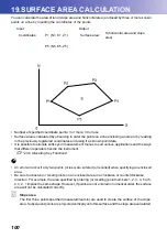
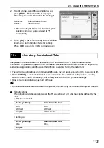
Страница 108: ...strument C 20 6 Allocating Key Functions G An error will occur if only two points or less are entered or recalled when specifying an enclosed area Be sure to observe or recall points on an enclosed ar...
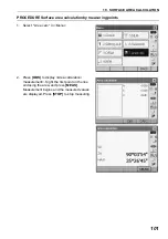
Страница 109: ...lation by measuring points 1 Select Area calc in Menu 2 Press OBS to display Area calculation measurement Sight the first point on the line enclosing the area and press MEAS Measurement begins and the...
Страница 110: ...firm The value of point 1 is set in Pt_01 4 Repeat steps 2 to 3 until all points have been measured Points on an enclosed area are observed in a clockwise or counterclockwise direction For example the...
Страница 111: ...103 19 SURFACE AREA CALCULATION 5 Press CALC to display the calculated area 6 Press OK to return to Area key in coord Press ESC or tap the cross in the top right corner to quit area calculation...
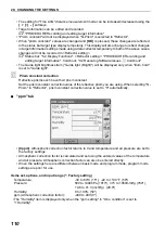
Страница 112: ...n can be accessed by pressing the CONFIG icon in Top The following chapters provide details of items in Configuration mode Communication settings C 10 CONNECTING TO EXTERNAL DEVICES Instrument configu...
Страница 113: ...ion When Sea level crn is set to No Distance on the rectangular coordinates system without correction Automatic tilt angle compensation mechanism The vertical and horizontal angles are automatically c...
Страница 114: ...nce using slope distance values As this horizontal distance does not take height above sea level into consideration performing spherical correction is recommended when measuring at high altitudes Sphe...
Страница 115: ...Auto Auto Backlight Off No 30sec 1min 5min 10min Key backlight Off On Reticle lev 0 to 5 level 3 EDM ALC Free Hold Guide pattern 1 simultaneous 2 alternating Laser pointer off No 1min 5min 10min 30min...
Страница 116: ...of ambient brightness and automatically sets backlight brightness accordingly Depending on ambient light conditions performance of this function may be sub optimal or the display may flicker between...
Страница 117: ...e displayed Set to Hold when the light beam used for measurement is stable but is frequently obstructed by obstacles such as people cars or tree branches etc preventing measurement from being performe...
Страница 118: ...l be displayed only when Illum hold is set to Guide light Prism constant correction Reflective prisms each have their prism constant Set the prism constant correction value of the reflective prism you...
Страница 119: ...rmal temperature and pressure conditions With constant pressure a temperature change of 1 C an index change of 1 ppm With constant temperature a pressure change of 3 6 hPa an index change of 1 ppm To...
Страница 120: ...ed when either Reflector or Prism const is selected in the EDM tab of EDM configurations 1 Press LIST to display a list of all recorded targets ADD Displays Reflector list Select the desired target fr...
Страница 121: ...preset to suit various applications and the ways that different operators handle the instrument The current tab allocations are retained until they are revised again even when the power is cut off Pr...
Страница 122: ...hic tab cannot be deleted PROCEDURE Allocating tabs 1 Select Customize to display Customize Select screen Select the measurement mode in which you want to allocate a tab Select Tab page Factory settin...
Страница 123: ...tabs The allocated tabs are stored in memory and Customize is displayed The newly allocated tabs appear in the relevant measurement screen It is possible to customize screen controls in Observation mo...
Страница 124: ...isplay Customize Select screen Select the measurement mode in which you want to customize screen controls Select Control 2 Press ADD to add a control drop down list Press DEL to delete the selected co...
Страница 125: ...rators handle the instrument The current softkey allocations are retained until they are revised again even when the FX is powered OFF Press CLEAR in Customize Select screen to return all customized c...
Страница 126: ...e in The capitalized letter in the softkey indicates the currently selected mode HOLD Hold horizontal angle release horizontal angle CALL Display final measurement data HVOUT T Output angle measuremen...
Страница 127: ...asurement mode in which you want to allocate a softkey Select Softkey 2 Select the desired tab All softkeys currently allocated to each page of that tab are displayed 3 Select the softkey whose alloca...
Страница 128: ...t icon allocations are retained until they are revised again even when the power is turned off Press CLEAR in Customize Select screen to return all customized configurations including tab pages screen...
Страница 129: ...using arrow key A blue arrow will indicate the selected position 3 Select the new icon for the selected icon position Select and change by double tapping Or Select using O G and tap Change ENT 4 Repea...
Страница 130: ...rounds off the value input by the digit of less than 0 004 feet 0 017 inch Inch Fraction of an inch Fraction of an inch is the unit used in the United States and expressed like the following example G...
Страница 131: ...ear when the FX is powered ON Input the password to continue Items set Old password Input current password New password Input the new password New password again Input the new password again Password...
Страница 132: ...surveying data in FX However if the data in the memory is important BE SURE TO TRANSFER IT TO A PERSONAL COMPUTER BEFORE PERFORMING A COLD BOOT To perform a cold boot while holding and S P press All...
Страница 133: ...ose a single surface target for distance measurement C Precautions for setting prism 11 FOCUSSING AND TARGET SIGHTING Calculation error During resection measurement the same point is registered multip...
Страница 134: ...REM measurement either the vertical angle has exceeded horizontal 89 or the measured distance is greater than 9999 999m Install the instrument station far from the target The instrument station coord...
Страница 135: ...AGES Tilt over range The tilt angle exceeds the tilt angle compensation range of the sensor Sight again within 1 Time out Measurement is not carried out in the allotted time Reset and sight the prism...
Страница 136: ...mpensation icon in star mode to display electric circular level G If the tilt sensor is misaligned the circular level is not adjusted correctly C 22 2 Tilt Sensor 2 Check the position of the bubble of...
Страница 137: ...el the tilt zero point error PROCEDURE Checking and adjusting 1 Carefully level the FX If necessary repeat the procedures to check and adjust the bubble levels 2 Select Inst cons in Configuration 3 Se...
Страница 138: ...strument and telescope through 180 9 Confirm that the values are in the adjustment range If both correction constants are within the range the current value 1 select YES to renew the correction angle...
Страница 139: ...h offset values fall within the range 10 adjustment is completed Press ESC to return to Instrument constants If one of the offset values Xoffset Yoffset exceeds 10 repeat the check and adjustment proc...
Страница 140: ...equent single face observations To measure the error make angular observations using both faces PROCEDURE 1 Select Inst cons in Configuration 2 Select Collimation 3 Sight the reference point in Face 1...
Страница 141: ...larity of the reticle to the horizontal axis 1 Carefully level the instrument 2 Align a clearly visible target the edge of a roof for example on point A of the reticle line 3 Use the fine motion screw...
Страница 142: ...4 While the telescope is in face right sight the center of the target and read out the horizontal angle A2 and the vertical angle B2 Example Horizontal angle A2 198 34 20 Vertical angle B2 269 30 00 5...
Страница 143: ...ey point precisely in the reticle of the optical plummet 2 Turn the upper part through 180 and check the position of the survey point in the reticle If the surveying point is still centered no adjustm...
Страница 144: ...ntered on the reticle even if the upper part of the instrument is rotated If necessary perform the adjustment again 7 Replace the optical plummet reticle cover The additive distance constant K of the...
Страница 145: ...alculate the average value 3 Place the FX at point C directly between points A and B and set up the reflective prism at point A 4 Precisely measure the horizontal distances CA and CB 10 times each and...
Страница 146: ...e center of the circle created by the rotating laser plummet beam Laser beam remains centered on the center of the target No adjustment necessary Laser beam strays from the center of the target Adjust...
Страница 147: ...r lower part of Fig A the up down adjustment is made as follows c Insert the provided hexagon key wrench into both the upper and lower screws d Slightly loosen the upper lower screw and tighten the lo...
Страница 148: ...he target center 9 Re attach the laser plummet adjustment cap Tightening each of the fine adjustment screws moves the laser plummet beam in the directions shown below Up Right Left Down Tighten Up scr...
Страница 149: ...are standard accessories Others are optional accessories sold separately for 101 102 and low temperature models By using the Y cable the FX can perform RS232C communication D sub 9 pin at the same tim...
Страница 150: ...t the reflective prism correctly and sight the center of the prism target accurately Each reflective prism 1 has its own prism constant value When changing prisms be sure to change the prism constant...
Страница 151: ...bble is off center adjust as follows 4 Correct half of the bubble displacement using levelling foot screw C 5 Correct the remaining half of the displacement by using the adjustment pin to rotate the p...
Страница 152: ...ew I Tubular compass CP7 Slide the tubular compass into the tubular com pass slot loosen the clamp screw then rotate the top part of the instrument until the compass nee dle bisects the index lines Th...
Страница 153: ...lter OF3A When sighting targets where glare is present solar observations for example attach it to the objective lens of the FX to protect its interior and the eyes of its operator The filter part can...
Страница 154: ...Degree Gon Mil selectable Minimum display FX 101 102 0 5 0 0001gon 0 002mil 1 0 0002gon 0 005mil selectable FX 103 105 107 1 0 0002gon 0 005mil 5 0 0010gon 0 020mil selectable Accuracy FX 101 1 0 000...
Страница 155: ...S50N K 4 1 3 to 300m 980ft 1 3 to 180m 590ft 3 Reflective sheet RS10N K 4 1 3 to 100m 320ft 1 3 to 60m 190ft 3 Compact prism CP01 1 3 to 2 500m 8 200ft Standard prism AP01AR X 1 1 3 to 4 000m 13 120ft...
Страница 156: ...00 hPa in 1hPa step 375 to 1 050 mmHg in 1mmHg step 14 8 to 41 3 inchHg in 0 1inchHg step ppm input range 499 to 499 ppm in 1 ppm step Prism constant correction 99 to 99 mm in 1 mm step 0mm fixed for...
Страница 157: ...e may vary with different paired devices No obstacles few vehicles or sources of radio emissions interference in the near vicinity of the instrument no rain Authentication Yes No selectable Wireless L...
Страница 158: ...tivity of levels Circular level 10 2 mm Electronic Circular levels Graphic display range 6 inner circle Digital display range 6 30 Optical plummet Image Erect Magnification 3X Minimum focus 0 3 m Lase...
Страница 159: ...surface 236mm 5 3mm from tribrach bottom Size with handle Display on one side 191 W X 174 D X 348 H mm Display on both sides 191 W X 190 D X 348 H mm Weight with handle and battery 5 7kg 12 3 lb 9 No...
Страница 160: ...le indexing method to Yes C 20 1 Observation Conditions V manual 0 set is displayed 2 Carefully level the instrument 3 Accurately sight a clear target with a distance of about 30m in the horizontal di...
Страница 161: ...or operated in conjunction with any other antenna or transmitter This equipment complies with FCC radiation exposure limits set forth for uncontrolled equipment and meets the FCC radio frequency RF Ex...
Страница 162: ...de la classe A est conforme a la norme NMB 003 du Canada Operation is subject to the following two conditions 1 this device may not cause interference and 2 this device must accept any interference in...
Страница 163: ...lass B R TTE Class 2 EU R TTE Class 2 R TTE Directive FX series Hereby TOPCON CORP declares that the above mentioned equipment is in compliance with the essential requirements and other relevant provi...
Страница 164: ...28 REGULATIONS 156 Australia C Tick China SRRC China Chinese Environment al Directive Region Country Directives Regulations Labels Declarations 23316...
Страница 165: ...ing parallax 50 G Guide light 11 H Hdist 105 Horizontal angle settings 64 70 I Inch Fraction of an inch 122 Instrument height mark 11 K Key backlight 109 L Laser pointer function 11 Laser pointer off...
Страница 166: ...http www topcon co jp GLOBAL GATEWAY http global topcon com Please see the attached address list or the following website for contact addresses 2012 TOPCON CORPORATION ALL RIGHTS RESERVED...