background image

34

BASIC OPERATIONS

BA

SI

C OPERATIONS

MEASUREMENT

6

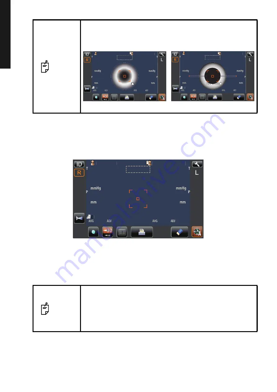
Align to make the Z alignment arrows short, and the measurement is carried out when the Z

alignment arrows reach minimum, and then the measurement value is displayed on the con-
trol panel. For displaying measurement values, refer to "DISPLAYING MEASUREMENT VAL-
UES"
 on page 35.

7

Hold the control lever and pull the main body to the operator side, then switch R or L and

repeat the same procedure from "SETTING THE SAFETY STOPPER" on page 29 to previous
item for the next eye measurement.

8

Tell the patient a measuring is end and leave from the instrument.

NOTE

• When the measuring head approaches patient's eye too much, "TOO

CLOSE" is displayed and when it keeps away from patient's eye too
much, "TOO FAR" is displayed. Using the control lever, move the measur-
ing head to a position where aligning is possible.

NOTE

• If Auto Shoot mode measurement does not work, press the measurement

switch when the alignment dot becomes minimum within the alignment
mark.
Auto Shoot mode measurement may not work depending on the cornea
condition.

• If the machine is moved before measurement values are displayed, it

might cause an incorrect measurement.

Patient ID

Patient ID

1

1

TOPCON̲TAROU

TOPCON̲TAROU

TOO FAR

TOO FAR

Auto Shoot

Patient ID

Patient ID

1

1

TOPCON̲TAROU

TOPCON̲TAROU

TOO CLOSE

Auto Shoot

Limit of movement in the backward direction

Limit of movement in the forward direction

Patient ID

Patient ID

3

3

3

3

15

15

15

15

15

15

15

15

1

1

TOPCON̲TAROU

TOPCON̲TAROU

14
[15]
16

14
[15]
16

15
17
14

15
17
14

0.499

0.499

0.500

0.500

1

1

1

1

Auto Shoot

Содержание CT-800

Страница 1: ...USER MANUAL COMPUTERIZED TONOMETER CT 800 ...

Страница 2: ......

Страница 3: ...ys and Safety Cautions Keep this Manual at hand for future reference Since this product is a precision instrument always use and keep it in a normally controlled living environment within a temperature range of 10 40 C humidity levels between 30 90 and an atmospheric pressure range of 700hPa 1 060hPa The instrument should also be placed away from direct sunlight To ensure smooth operation install ...

Страница 4: ...f this manual may be copied or reprinted in whole or in part without prior written permission 2 The contents of this manual are subject to change without prior notice and without legal obligation 3 The contents of this manual are correct to the best of our knowledge Please inform us of any ambiguous or erroneous descriptions missing information etc 4 Original Instructions This manual was originall...

Страница 5: ...NTS 12 FUNCTION BUTTON 13 MONITOR SCREEN 14 MEASUREMENT SCREEN 14 SETUP SCREEN 14 ALL DATA SCREEN 15 PATIENT ID INPUT SCREEN 15 PRINTER OUTPUT 16 STANDARD ACCESSORIES 19 PREPARATIONS INSTALLATION 20 CONNECTING POWER CABLE 20 CONNECTING EXTERNAL I O TERMINALS 21 DATA OUTPUT 21 DATA INPUT 21 PRINTER PAPER SETTING 22 RECOVERY FROM POWER SAVE STATUS 23 BASIC OPERATIONS OPERATION FLOW CHART 24 PREPARAT...

Страница 6: ...N OPERATIONS 49 RETURNING TO THE MEASUREMENT SCREEN 51 LIST OF SETUP ITEMS 52 INITIAL SETTINGS 52 INTERNAL PRINTER 54 DATA COMMUNICATION COMM 55 LAN CONNECTION LAN 55 OPERATOR SETTINGS 55 SPECIAL 55 MAINTENANCE DAILY CHECKUPS 56 CLEANING THE INSTRUMENT 56 CLEANING THE INTRAOCULAR PRESSURE MEASURING WINDOW 56 CLEANING THE MEASURING NOZZLE AND THE GLASS INSIDE THE MEASURING NOZZLE 57 CLEANING THE CO...

Страница 7: ... CONDITIONS FOR PACKAGING IN STORAGE 66 ENVIRONMENTAL CONDITIONS FOR PACKAGING IN TRANSPORTATION 67 ELECTRIC RATING 67 SAFETY DESIGNATIONS PER IEC 60601 1 STANDARD 67 DIMENSIONS AND WEIGHT 68 OPERATION PRINCIPLE 68 CHECKPOINTS FOR MAINTENANCE 68 DISPOSAL 68 ELECTROMAGNETIC COMPATIBILITY 69 REQUIREMENTS FOR THE EXTERNAL DEVICE 72 PATIENT S ENVIRONMENT 73 REFERENCE OPTIONAL ACCESSORIES 74 SHAPE OF P...

Страница 8: ...enting Electric Shocks and Fires To avoid fire and electric shock install the instrument in a dry place free of water and other liquids To avoid fire and electric shock do not put cups or other containers with liquids near the instrument To avoid electric shocks do not insert metal objects into the instrument body through the vent holes or gaps To avoid fire in the event of an instrument malfuncti...

Страница 9: ...or more than 2 hours will exceed the safety guideline Preventing Electric Shocks and Fires To avoid injury by electric shock do not open the cover For repair call your service engineer Electromagnetic Compatibility EMC This instrument has been tested with 100 120 230V and found to comply with IEC60601 1 2 Ed 3 0 2007 This instrument radiates radio frequency energy within standard and may affect ot...

Страница 10: ...WINDOW on page 56 CLEANING THE MEASURING NOZZLE AND WINDOW GLASS INSIDE THE NOZZLE Regarding the measuring nozzle and the glass surface inside the measuring nozzle cleaning is allowed For details see CLEANING THE MEASURING NOZZLE AND THE GLASS INSIDE THE MEASURING NOZ ZLE on page 57 DISCLAIMERS TOPCON is not responsible for damage due to fire earthquakes actions or inactions of third persons or ot...

Страница 11: ...or moderate injury NOTES Useful functions to know Paying attention to these will prevent the noted problems Symbol IEC ISO Publication Description Description French IEC 60417 5032 Alternating Current Courant alternatif IEC 60417 5008 Off power disconnection from the main power supply Éteint courant coupure avec le secteur IEC 60417 5007 On power connection to the main power supply Allumé courant ...

Страница 12: ...lez à configurer l arrêt de sécurité Si non cela peut provoquer des blessures en heurtant l œil ou le nez du patient avec l instrument 3 CAUTION Be careful not to hit the patient s eyes or nose with the instrument during operation The patient may be injured PRÉCAUTION Prendre garde de ne pas frapper les yeux ou le nez du patient avec l instrument pen dant l opération 4 CAUTION Pay much attention n...

Страница 13: ...ase stopper released position Base stopper fixed position Control panel Measuring head External I O terminal Main Body Section Printer cover open button Printer cover Control lever Power Unit Section Measurement switch Base stopper Forehead rest Measuring window Eye height mark Chinrest Chinrest up down knob POWER switch Power inlet Nozzle cap Chinrest tissue pin Nozzle cap holder Measuring nozzle...

Страница 14: ...play Shows the measured eye is R Right eye or L Left eye The measured eye is framed in orange Air check button Checks that the measurement system of the instrument oper ates properly NOTE The control panel is a touch panel Do not use any sharp tools e g ball point pen Do not touch two points on a control panel simultaneously Tap To select any relevant item Touch the control panel softly with a fin...

Страница 15: ... this button may allow the measurement When the button is selected IOL is displayed on the control panel and the selected button is framed in orange 30 60 button Switches between 1 30 range and 1 60 range All data button Displays all measurement data on the screen Print out button Displays on measurement stand by and prints measurement results Tap the button when no measurement data is present to ...

Страница 16: ... pressure value Patient No Patient ID Device ID number TONO measurement value Number of TONO measure ment times Display unit mark of cornea thickness Outeralignment mark TONO adjusted average value TONO average value PACHO input value Sign of PACHO entered 00 not entered 01 entered OFF ON Return Initial Print Comm LAN Special Operator ID 1 3 Buzzer sound Auto Shoot Printer output Show Pacho value ...

Страница 17: ...0 555mm PACHO 0 555mm 1 2 3 4 5 6 7 8 9 10 AVG LEFT RCEJQ Measurement item Right Left eye titles Exit button Measurement count average Measurement result values Patient ID 13 1 7 ψ 2 3 4 5 6 8 9 0 φ BS z m x c v b n space 㧚 q u w e r t y i o p Del a j s d f g h k l _ OK Cancel Reset Caps Capital lock key Reset button OK button Cancel button Keyboard Enter window ...

Страница 18: ...parenthesis notation CT 010017 OID TOPCON_TAROU NAME 2012_01_01 TONO DATA PACH DATA R 13 M 8 M 7M 7 0 L 9 7 10 9 0 hPa AVG R 13 M 8 M 7M 7 0 L 9 7 10 9 0 ADJ AVG R 541 L IOP ADJ FORMULA A 520 B 120 541 um um AM 11 00 TOPCON Hello World NO Patient ID SN 0000001 01 Patient No Barcode Name entry column Operator ID Display unit of CCT Average value of adjusted Tono value Tono average value on display ...

Страница 19: ...orld Patient No Barcode Name entry column Operator ID Adjusted Tono value hPa Patient No Patient ID when Patient ID is input Device ID number Display unit at Pacho Average value of adjusted measurement value hPa Tono average value on display hPa Tono value on display unit hPa Tono value of IOP adjustment by CCT Message column Topcon Logo mark Center CCT Base IOP Adjustment Coefficient Device ID nu...

Страница 20: ...J ERR 13M 16 14M AM 11 00 NO Patient ID SN 0000001 01 IOP ADJ FORMULA A 520 B 120 TOPCON Hello World Device ID number Serial number Title of TONO value Title of Pacho value Title of IOP ADJ Formula Patient No Barcode Message column Topcon Logo mark Patient No Patient ID when Patient ID is input Device ID number Name entry column Operator ID Tono average value on display unit hPa Tono value on disp...

Страница 21: ...cluded quantity Power cable 1 Chinrest tissue pin 2 Printer paper 2 Monitor cleaner 1 Chinrest tissue 1 Dust cover 1 Accessory case 1 User Manual Instruction Manual Unpacking and Assembling Cleaning Procedure 1 each Nozzle cap 1 Blower 1 Applicator 1 Plastic container 1 ขᛒ ᦠ ࡁࡦࠦࡦ ࠢ ࠗࡊ ࡁࡔ ขᛒ ᦠ ࡁࡦࠦࡦ ࠢ ࠗࡊ ࡁࡔ CT 800 ...

Страница 22: ...se harm to his back or injury by falling parts Also holding areas other than the bottom and holding the External I O terminal cover may cause injury as well as damage to the instrument To prevent damage and injuries do not install the instrument on an uneven unsteady or sloped surface When setting an instrument on an instrument table pay attention not to injury the patient s fingers between the in...

Страница 23: ...ion cable to the PC etc DATA INPUT This product can be connected to a bar code reader and other external devices via USB 1 Connect the connection cable to the USB input terminal of the instrument 2 Connect the other end of the connection cable to the external device CAUTION To avoid electric shock do not touch the external connection terminal and the patient at the same time NOTE When connecting t...

Страница 24: ...ry in case of malfunction including a paper jam be sure to shut off the power before attempting to repair it To avoid potential injury do not touch the printer body including metal parts or the paper cutter while the printer is in operation or when replacing the printer paper NOTE If you insert the printer paper backwards printing will not start Please push the printer cover OPEN button using your...

Страница 25: ...the printer cover using your right thumb while placing your index and middle fingers on the projecting part which is in reverse side below the printer cover OPEN switch Unexpected movement is avoided when closing the printer cover In case the printer cover is not firmly closed printing will not start and CLOSE PRT COVER will be displayed on the monitor screen A 58mm wide paper roll example TP 50KJ...

Страница 26: ...power CHECKING THE MEASURING NOZZLE PREPARATION BEFORE MEASUREMENT page 25 to 29 page 25 AIR CHECK page 26 TURNING ON THE INSTRUMENT SETTING THE PATIENT ID page 27 page 28 PATIENT POSITIONING SETTING THE SAFETY STOPPER page 29 MEASUREMENT page 30 CLEARING MEASUREMENT VALUES page 37 page 36 PRINTOUT OF MEASURE MENT VALUES OPERATION OF AFTER USE page 41 DISPLAYING ALL MEASURE MENT DATA page 38 ...

Страница 27: ...HECKING THE MEASURING NOZZLE 1 Remove the nozzle cap The removed nozzle cap can be put into nozzle cap holder of the main body side Please set bended rim side of the nozzle cap to the bottom 2 Check if there is any foreign matter on and around the measuring nozzle If there is any turn OFF the switch clean it off and then turn ON the switch For cleaning see CLEANING THE MEASURING NOZZLE AND THE GLA...

Страница 28: ... on the control panel 4 Press the button return to Measurement screen NOTE If abnormal action or abnormal action is displayed the condition is not normal Check if there is any object before the measuring nozzle If there is any remove it press the button and do the check again If there is no object a failure is suspected Turn the switch to OFF unplug the power cable and call your dealer or TOPCON a...

Страница 29: ...tient ID using the keyboard on the screen 4 Return to the Measurement screen and confirm that the patient ID is updated NOTE If Display of patient ID is set to OFF in the initial setting the patient No patient ID is not displayed on the measurement screen ID 2 2 Auto Shoot Patient ID 13 Operator ID 13 Patient ID 13 Operator ID 13 Patient_ID Keyboard Patient ID Patient ID Auto Shoot 1 1 ...

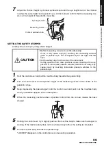
Страница 30: ...er Tell this to the patient too To avoid injury when operating the machine be careful about the cover not to catch fingers of the patient Tell this to the patient too To avoid injury by raising falling or dropping the instrument do not apply the strong power downward on the chinrest When operating the instrument be careful that the instrument does not touch the patient s lip or nose If touched cle...

Страница 31: ... 4 When the measuring nozzle reaches a position 8 9mm from the cornea release the base stopper 5 Holding the control lever try to slightly push out the machine body to make sure the stopper is working If the machine body does not move forward any further the setting is completed 6 Pull the machine body towards the operator fully LOCKED disappears in the control panel so measuring is possible CAUTI...

Страница 32: ...hed clean the instrument as specified in CLEANING THE INSTRUMENT on page 56 NOTE Auto Shoot mode measurement may not be possible in case the eyelid and the eyelashes cover the pupil If this occurs the operator should tell the patient to open their eyes as wide as possible or lift the eyelid to allow for measurement Auto Shoot mode measurement may not be possible due to frequent blinks or existing ...

Страница 33: ... con trol level to each direction The main body position can be fine adjusted vertically by turning the control level right up and left down CAUTION To avoid injury when operating the machine for measurement and control panel operation be careful not to approach the finger to space of movable part Operating the control lever for front back right and left adjustment Operating the control lever for ...

Страница 34: ... position in all directions so that the alignment dot point comes within the alignment mark 01 01 Patient ID Patient ID TOPCON_TAROU TOPCON_TAROU mm mm T P 00 00 00 00 mmHg mmHg AVG AVG ADJ ADJ mm mm T P 00 00 00 00 mmHg mmHg AVG AVG ADJ ADJ AutoShoot ID L R 30 30 60 60 Patient ID Patient ID 1 1 TOPCON TAROU TOPCON TAROU Auto Shoot 12 00 12 00 01 01 VD VD 0000100001000 0000100001000 0000100001000 ...

Страница 35: ...A1 A1 AutoShoot AutoShoot R S C A K R1 R1 R2 R2 A1 A1 ID L R 0 3 0 3 0 3 0 3 0 3 0 3 0 3 0 3 R K R K KRT KRT REF REF Patient ID Patient ID 1 1 TOPCON TAROU TOPCON TAROU Auto Shoot Z alignment arrows 12 00 12 00 01 01 VD VD 0000100001000 0000100001000 0000100001000 0000100001000 mm mm R S C A K R1 R1 R2 R2 A1 A1 AutoShoot R S C A K R1 R1 R2 R2 A1 A1 ID L R 0 3 0 3 0 3 0 3 0 3 0 3 0 3 0 3 R K R K KR...

Страница 36: ...nd when it keeps away from patient s eye too much TOO FAR is displayed Using the control lever move the measur ing head to a position where aligning is possible NOTE If Auto Shoot mode measurement does not work press the measurement switch when the alignment dot becomes minimum within the alignment mark Auto Shoot mode measurement may not work depending on the cornea condition If the machine is mo...

Страница 37: ...display low reliability numerical data with are not added to the average value calculation However if all measurement data are numerical data with the average value calculation is done using these data For explanation of the messages on the control panel screen refer to MESSAGE LIST on page 62 When data is printed out the M mark is printed on the value measured in auto shoot mode off Patient ID Pa...

Страница 38: ...asti cizer PVC etc To avoid discoloring of the printer paper particularly the recording area after pasting use water soluble glue and not one containing solvent Since the printer paper is thermosensitive it is not suitable for keeping records for a long period If necessary prepare copies separately NOTE When a red line is printed at the edge of the printer paper replace it with a new one For detai...

Страница 39: ...alues is not required be sure to clear the measurement values for a next patient 1 Tap the button on the control panel All measurement values of both eyes are cleared ALL CLEAR Patient ID Patient ID 3 3 3 3 15 15 15 15 15 15 15 15 1 1 TOPCON TAROU TOPCON TAROU 14 15 16 14 15 16 15 17 14 15 17 14 0 499 0 499 0 500 0 500 Auto Shoot ...

Страница 40: ...m Display unit in intraocular pressure measurement mmHg Setup item Display unit in intraocular pressure measurement hPa ALL DATA DISPLAY Patient ID Patient ID 1 1 TOPCON TAROU TOPCON TAROU 3 3 3 3 15 15 15 15 15 15 15 15 14 15 16 14 15 16 15 17 14 15 17 14 0 499 0 499 0 500 0 500 Auto Shoot TONO mmHg TONO mmHg 1 2 3 4 5 6 7 8 9 10 AVG RIGHT 1 2 3 4 5 6 7 8 9 10 AVG LEFT RCEJQ PACHO 0 555mm PACHO 0...

Страница 41: ...value measured by using the measurement switch in auto shoot mode the color of a character turns to yellow TONO mmHg ADJ mmHg TONO mmHg ADJ mmHg 1 2 3 4 5 6 7 8 9 10 AVG RIGHT 1 2 3 4 5 6 7 8 9 10 AVG LEFT RCEJQ PACHO 0 555mm PACHO 0 555mm TONO hPa ADJ hPa TONO mmHg ADJ mmHg TONO hPa ADJ hPa TONO mmHg ADJ mmHg 1 2 3 4 5 6 7 8 9 10 AVE RIGHT PACHO 0 555mm PACHO 0 555mm 1 2 3 4 5 6 7 8 9 10 AVE LEFT...

Страница 42: ...O TONO hPa ADJ hPa TONO mmHg ADJ mmHg PACHO mm TONO hPa ADJ hPa TONO mmHg ADJ mmHg PACHO mm 1 2 3 4 5 6 7 8 9 10 AVG RIGHT 1 2 3 4 5 6 7 8 9 10 AVG 18 LEFT RCEJQ PACHO 0 000mm PACHO 0 000mm 24 ERR ERR ERR ERR ERR ERR ERR ERR ERR ERR ERR ERR 22 17 24 18 24 18 23 17 24 18 25 25 19 19 TONO hPa ADJ hPa TONO mmHg ADJ mmHg PACHO mm TONO hPa ADJ hPa TONO mmHg ADJ mmHg PACHO mm 1 2 3 4 5 6 7 8 9 10 AVG RI...

Страница 43: ...cable from a 3 pin AC inlet with grounding 4 Fit the nozzle cap to the measuring nozzle NOTE When external devices are connected to external I O terminals turn off the power of these devices too If power switch is provided NOTE When the instrument is not used for a long period unplug the power supply cable and detach the cable connected to the external I O terminal POWER ...

Страница 44: ...lar pressure is high switch it to 1 60 The default setting is 1 30 upon power on 1 Tap the button of the measurement screen and set the measuring range NOTE Adjust the height of the instrument table so that the patient can sit com fortably Otherwise correct measurement values may not be obtained Do not perform measurement if the patient stops breathing or is nervous Otherwise correct measurement v...

Страница 45: ...fficient out of the measuring range When alignment is within the measuring range in all directions front rear right left top bottom When the measuring head is at the limit of movement in the forward direc tion TOO CLOSE is displayed and when it is at the limit of movement in the backward direction TOO FAR is displayed Using the move the measuring head to a position where aligning is possible As th...

Страница 46: ...nd if the machine is completely off the alignment range the message TOO FAR is displayed The number of arrows are reduced accordingly as the optimal alignment reference position comes closer If the alignment reaches the measuring range the arrow is displayed in aqua color 12 00 12 00 01 01 VD VD 0000100001000 0000100001000 0000100001000 mm mm R S C A K R1 R1 R2 R2 A1 A1 R S C A K R1 R1 R2 R2 A1 A1...

Страница 47: ... 29 to previous item for the next eye measurement Patient ID Patient ID 1 1 TOPCON TAROU TOPCON TAROU TOO CLOSE Patient ID Patient ID 1 1 TOPCON TAROU TOPCON TAROU TOO FAR TOO FAR Patient ID Patient ID 1 1 TOPCON TAROU TOPCON TAROU TOO FAR TOO FAR Too close Too far Positioning is incorrect at all Outward Z alignment arrows purple Inward Z alignment arrows Green Z alignment arrows are not appeared ...

Страница 48: ...n if you seem to get correct alignment the alignment mark does not become In this case please carry out a measurement after confirming surely that the alignment is performed correctly The alignment mark may not become according to patient s cornea condition NOTE In TONO average value display low reliability numerical data with are not added to the average value calculation However if all measureme...

Страница 49: ...bar code reader etc via the USB 1 Check the connection of USB IN For connection refer to CONNECTING EXTERNAL I O TERMINALS on page 21 2 Input ID numbers from the external device The inputted ID numbers are displayed on the screen OUTPUT USING LAN This instrument can output data to a PC etc via the LAN interface 1 Connect the network cable to LAN OUT For connection refer to CONNECTING EXTERNAL I O ...

Страница 50: ...N the switch 3 Tap the button on the control panel The SETUP screen is displayed POWER SETTINGS Patient ID Patient ID 1 1 TOPCON TAROU TOPCON TAROU Auto Shoot OFF ON Return Initial Print Comm LAN Special Operator ID 1 3 Buzzer sound Auto Shoot Printer output Show Pacho value Show Tono average Show Adj value Patient No reset Display of patient ID ON ON ON ON OFF ON ON ON Back Page button Page displ...

Страница 51: ...up down buttons and ten key would be displayed INDEX Return Initial Print Comm LAN Special Operator ID 1 3 Buzzer sound Auto Shoot Printer output Show Pacho value Show Tono average Show Adj value Patient No reset Display of patient ID NEXT PAGE BACK PAGE Initial Print Comm 1 3 Buzzer sound Auto Shoot Printer output CURRENT CONDITION OPTIONS OFF ON Initial Print Comm LAN 1 3 Buzzer sound Auto Shoot...

Страница 52: ...torID Special Return 28 3 3 IOP Adjustment Center CCT Base Adjustment Coefficient R L or OD OS Control panel brightness Shaded character Meas data recording way IOL LED Brightness OFF 545 500 R L ON LEVEL 4 Data on cre 28 Up Down buttons OK BS 192 168 0 1 7 4 1 0 8 5 2 9 6 3 AC OK CANCEL 1 1 NULL OFF FIX 0 0 0 0 0 0 0 0 0 0 0 0 0 0 0 0 0 0 0 0 LAN connection Shared Folder Setting IP Address Settin...

Страница 53: ...NING TO THE MEASUREMENT SCREEN 1 Tap the button 2 The Measurement screen is displayed Return Return Special Show Tono average Show Adj value Patient No reset Display of patient ID O Patient ID Patient ID 1 1 TOPCON TAROU TOPCON TAROU Auto Shoot ...

Страница 54: ...not displayed ON ON Adjusted value is displayed Patient No reset OFF Patient No is not reset upon power on OFF ON Patient No is reset upon power on Display of patient ID OFF Patient ID is not displayed ON ON Patient ID is displayed Patient ID Mandatory OFF Patient ID is not required OFF ON Patient ID is required Device ID number 1 99 Set by ten key display Sets the Device ID number 1 Display of De...

Страница 55: ...ess base value Used when IOP adjustment is ON A Center CCT Base 545 Adjustment Coefficient 0 9999 Set by ten key display Sets the adjustment coefficient Used when IOP adjustment is ON B Adjustment Coefficient 500 R L or OD OS R L Right left eyes is displayed by R L R L OD OS Right left eyes is displayed by OD OS Control panel brightness Setup of the brightness of control panel LEVEL 1 dark The bri...

Страница 56: ...s printed Message print OFF Message is not printed OFF ON Message is not printed Input message Set by keyboard display String of up to 72 characters NULL Line space Set by keyboard display Line space is set in dot units 0 Auto Cut OFF Auto cut is not carried out ON ON Auto cut is carried out Print Layout R L TONO measurement value and PACHO measurement value are separately printed SIMPLE DATA The ...

Страница 57: ...g terminated null char Set by keyboard display Path and permission to the shared folder is set NULL IP Address Setting FIX Assign IP address manually FIX AUTO Assign IP address automatically IP Address 0 0 0 0 Set by ten key display IP address of PC to output data 0 0 0 0 Subnet Mask 0 0 0 0 Set by ten key display Subnet mask address of CT 1P CT 1 0 0 0 0 Default Gateway 0 0 0 0 Set by ten key dis...

Страница 58: ... panel screen 1 Prepare the ethanol 2 Using a blower remove dust and dirt from the glass surface 3 Moisten the applicator with ethanol 4 Wipe the glass surface lightly with the applicator from the center outward 5 Use a new applicator and wipe the glass surface in a similar manner repeat this several times CAUTION To clean the measuring window glass measuring nozzle and the glass inside the measur...

Страница 59: ...ator a few times 4 Use a new applicator and wipe the glass surface in a similar manner repeat this a few times 5 If the fixation target is clearly seen cleaning is completed If stains cannot be removed easily call your dealer NOTE When the intraocular pressure measuring window becomes stained CLEAN THE MEASURING WINDOW GLASS is displayed on the control panel screen CAUTION To clean the intraocular...

Страница 60: ... at the address listed on the back cover USER MAINTENANCE ITEM Product name Product code Product name Product code Chinrest tissue 40310 4082 Applicator 41601 8606 Monitor cleaner 44800 1001 Printer paper 44800 4001 Dust cover 42360 9002 Item Inspection time Contents Inspection Before using The instrument works properly The objective lens must be free of stains and or flaws Confirm whether the for...

Страница 61: ...tting a printer paper keep a patient s face away from the instrument Some part of the instrument may touch the patient s lip or nose if the printer button is pressed To avoid potential injury in case of malfunction including a paper jam be sure to shut off the power before attempting to repair it To avoid potential injury do not touch the printer body including metal parts or the paper cutter whil...

Страница 62: ...60 MAINTENANCE REPLACING THE CHINREST TISSUE PAPER When the chinrest tissue paper has run out pull off the chinrest pins and replace it with new tissue paper Chinrest pins Chinrest tissue paper ...

Страница 63: ...e stain still remains moisten the monitor cleaner with water and then wipe off the stain CAUTION Do not use or apply any aerosol type cleaner near the instrument If a drop of cleaner remains inside the measuring nozzle the patient s eye may be injured during measurement NOTE Do not clean plastic parts with solvents Benzine thinner ether and gasoline may cause discoloring and decomposition NOTE Sin...

Страница 64: ... when the setting Operator ID request is ON but the operator ID is not inputted Enter the operator ID and then request the output operation LAN hostname error Failed to resolve the host name of the destination to be connected with the shared folder Confirm the inputted host name or DNS server address LAN mount error Failed to connect to the shared folder Confirm the address folder name user name a...

Страница 65: ...r Confirm abnormal action of air check Displayed when an anomaly occurred during air check Check the measuring nozzle for any foreign matter First Octet is 1 223 Range Displayed when the first octet of IP address default gateway primary DNS server or secondary DNS server is set to a value out of the specified input range Value is irregular Input valid value Displayed when the octet is set to a val...

Страница 66: ...ING To avoid electrical shock do not open the instrument All service should be performed by a qualified service engineer CHECK LIST Trouble Condition Check Page Control panel does not turn on Is power cable unplugged 20 Is power cable connected to the instrument 20 Control panel is not clear The image is dark Adjust the brightness by Control panel Brightness Adjust 53 Any trouble is found in a mov...

Страница 67: ...uring range 1 to 60mmHg Display unit 1mmHg step display Average value 1mmHg 0 1mmHg step display Measuring range 1 to 30 1 to 60mmHg 2 step display External I O terminal USB for Import RS 232C for Export LAN for Export NOTE Essential performance Measurement must be performed correctly Monitor screen display must not be distorted ...

Страница 68: ...Air pressure 700hPa to 1060hPa THIS INSTRUMENT DOES NOT MEET THE TEMPERATURE REQUIREMENTS OF ISO 15004 1 FOR STORAGE DO NOT STORE THIS INSTRUMENT IN CONDITIONS WHERE THE TEMPERATURE MAY RISE ABOVE 40 C OR FALL BELOW 10 C 2 When storing the instrument ensure that the following conditions are met 1 The instrument must not be splashed with water 2 Store the instrument away from environments where air...

Страница 69: ...he reliability particularly of leak current patient measuring current and protective utility con nection in case of Class I equipment Degree of protection against harmful intrusion of water IEC 60529 IPX0 This product does not provide protection against intrusion of water The degree of protection against harmful ingress of water defined in IEC 60529 is IPX0 Classification by sterilization disinfec...

Страница 70: ...with finger prints dust etc 4 If the measuring window is soiled clean it following the CLEANING THE MEASURING NOZZLE AND THE GLASS INSIDE THE MEASURING NOZZLE instructions on page 57 DISPOSAL When disposing of the instrument and or parts follow local regulations for disposal and recycling NOTE This symbol is applicable for EU member countries only To avoid potential damage to the environment and p...

Страница 71: ...ther than those specified may result in increased EMISSION or decreased IMMUNITY of the EQUIPMENT or SYSTEM Item Article code Cable Shielded Ferrite Core Length m AC power cord for AC230V 424122090 NO NO 3 0 LAN Cable YES YES 3 0 Serial Cable YES NO 5 0 AC power code for PC NO NO 1 8 Keyboard cable NO NO 1 8 Mouse cable NO NO 1 8 RGB cable YES YES 1 8 AC power code for Display NO NO 1 8 USB Cable ...

Страница 72: ...5 1 kV line s to line s 2 kV line s to earth 1 kV line s to line s 2 kV line s to earth Mains power quality should be that of a typical commercial or hospital environment Voltage dips short interruptions and Voltage variations on power supply input lines IEC 61000 4 11 5 Ut 95 dip in Ut for 0 5 cycle 40 Ut 60 dip in Ut for 5 cycles 70 Ut 30 dip in Ut for 25 cycles 5 Ut 95 dip in Ut for 5 sec 5 Ut ...

Страница 73: ...ixed RF transmitters as determined by an electromagnetic site survey a should be less than the com pliance level in each frequency range b Interference may occur in the vicinity of equipment marked with the following symbol NOTE 1 NOTE 2 At 80 MHz and 800 MHz the higher frequency range applies These guidelines may not apply in all situations Electromagnetic propagation is affected by absorp tion a...

Страница 74: ...user of the CT 800 can help prevent electromagnetic interference by maintaining a minimum distance between portable and mobile RF communications equipment transmitters and the CT 800 as recommended below according to the maximum output power of the communications equipment Rated maximum output power of transmitter W Separation distance according to frequency of transmitter m 150kHz to 80MHz d 1 2 ...

Страница 75: ...o IEC60601 1 If you are compelled to use any device not conforming to IEC60601 1 use an insulation transformer or the common protective earth system Note 1 Use the device conforming to IEC60950 1 CAUTION Don t connect an additional power strip or an extension cord to the system Don t connect the device which is not recognized as one compo nent of the system Devices applicable to the patient s envi...

Страница 76: ...consumption 150VA 100 120V 220 240V SHAPE OF PLUG Country Voltage frequency Shape of plug Mexico 110V 50Hz Type C E Argentina 220V 60Hz Type A Peru 220V 60Hz Type A Venezuela 110V 50Hz Type C E Bolivia Paraguay 220V 60Hz Type A Most common Type H Infrequently Chile 220V 60Hz Type A Colombia 110V 50Hz Type C Brazil 220V 60Hz 127V 60Hz Type A Type C Ecuador 110V 50Hz Type C E USA 120V 60Hz Type A Ho...

Страница 77: ...stated above for the Licensed Program provided that the Recipient shall follow the provisions set forth in Article 3 Paragraph 1 when Redistributing the Derived Program Article 3 Restriction The license granted in the preceding Article shall be subject to the following restrictions 1 If a Derived Program is Redistributed pursuant to Paragraph 4 and 7 of the preceding Article the following conditio...

Страница 78: ......

Страница 79: ...late Period of use Please inform us of the date of purchase Defective condition Please provide us with as much detail as possible COMPUTERIZED TONOMETER CT 800 USER MANUAL 2014 version 2014 02 100LW0 Date of issue February 3rt 2014 Published by TOPCON CORPORATION 75 1 Hasunuma cho Itabashi ku Tokyo 174 8580 Japan 2014 TOPCON CORPORATION ALL RIGHTS RESERVED ...

Страница 80: ...78 COMPUTERIZED TONOMETER CT 800 41628 95010 Printed in Japan 1402 100LW0 ...

Отзывы: