Assembly
1. Be sure all parts are clean and free of any abrasive.
2. Press front bearing (700-7) into front bearing support (550-1-BTB).
3. Slip bearing cover (550-25) into front bearing support and onto front bearing.
4. Install snap ring (550-21) into groove of front bearing support with use of snap ring pliers.
5. Support front bearing assembly on a suitable drill block. Press the spindle (550-8) through the bearing up to the shoulder with
an arbor press.
6. Slide front endplate (550-7) over spindle and up to front bearing support.
7. Place key (550-10) into key slot of spindle.
8. Clamp spindle holder (1100-650) in vise vertically. Align key slot in holder with key of spindle and slide spindle assembly through.
9. Thread wheel flange (550-12B) onto spindle threads and tighten. Remove from vise.
10. Secure motor assembly into vise vertically with rear of motor toward upward direction. Clamp onto flats of wheel flange (550-12B).
11. Align the cylinder pin hole in bearing support (550-1-BTB) and front endplate (550-7).
12. Slide rotor (550-5) over spindle and key.
13. Insert five blades (550-6).
14. Place cylinder (550-2) over rotor with long dowel pin toward downward direction. Dowel pin goes through hole in front endplate and
front bearing support.
15. Place rear endplate (550-3) over cylinder. Locate the short dowel pin of the cylinder in the small hole of rear endplate.
16. Press bearing (700-9) into rear endplate with bearing driver (1100-808).
17. Install lock ring (1000-5) onto spindle with use of snap ring pliers. (There is no groove.)
18. Prior to reassemble inspect governor for gouges, nicks or dents. Oil the governor and inside of motor. Screw governor (AA-550-XX)
into end of spindle and tighten with governor wrench (1100-825). (left hand thread).
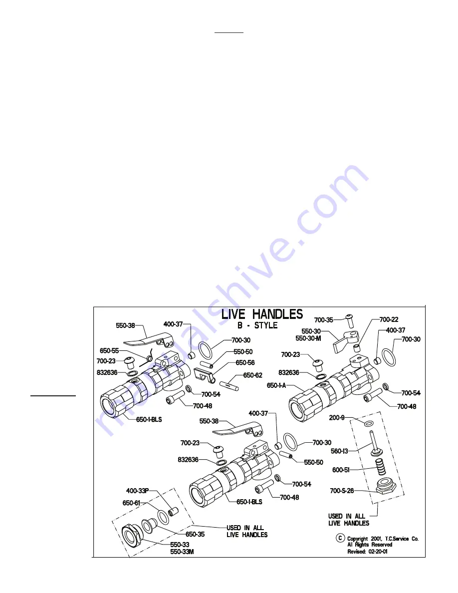
19. Assemble live handle if this was inspected or repaired.
20. Install live and dead handles to case (560-1).
21. Secure tool in a vise with motor axis in horizontal position. Clap onto the dead handle (550-1C) of grinder.
22. Place gasket (550-13) in rear face of case.
23. Slide the motor assembly into case. The motor assembly must be kept straight to install into the case easily. Try to maintain align-
ment as best as possible.
24. Line up guard with motor holes. Install as shown on page 8 of this booklet. Install 4 bolts (700-47A) and lock washers (700-46).
Tighten bolts down until snug then back off 1/2 turn.
25. Connect tool to air supply and apply air in several short bursts.
26. Now run tool and tighten down bolts evenly. (Alternating from corner to corner.)
27. Check RPM with a reliable tachometer. Tool must run at or below speed stamped on the tool.
Governors
The governors are
warranted for the
life of the tool.
(Execpt in cases
of abuse)
Please return the
governor to the
manufacturer for
warranty repair or
replacement.


