Toa WT-D5800 Скачать руководство пользователя страница 24

24

9. CONDUCTINg A SpECTRUM SCAN

The Spectrum Scan function checks the strength of radio wave in the specified frequency range and displays 

the result. It measures the signal reception for each frequency by receiving the radio wave in the specific 

interval in the specified frequency range. 

When the sound is disrupted, it simply checks for any interference within the specified frequency range without 

using any special measuring equipment.

The Channel Scan function (

p. 11

) also checks for any interference in the channel of the specified bank.

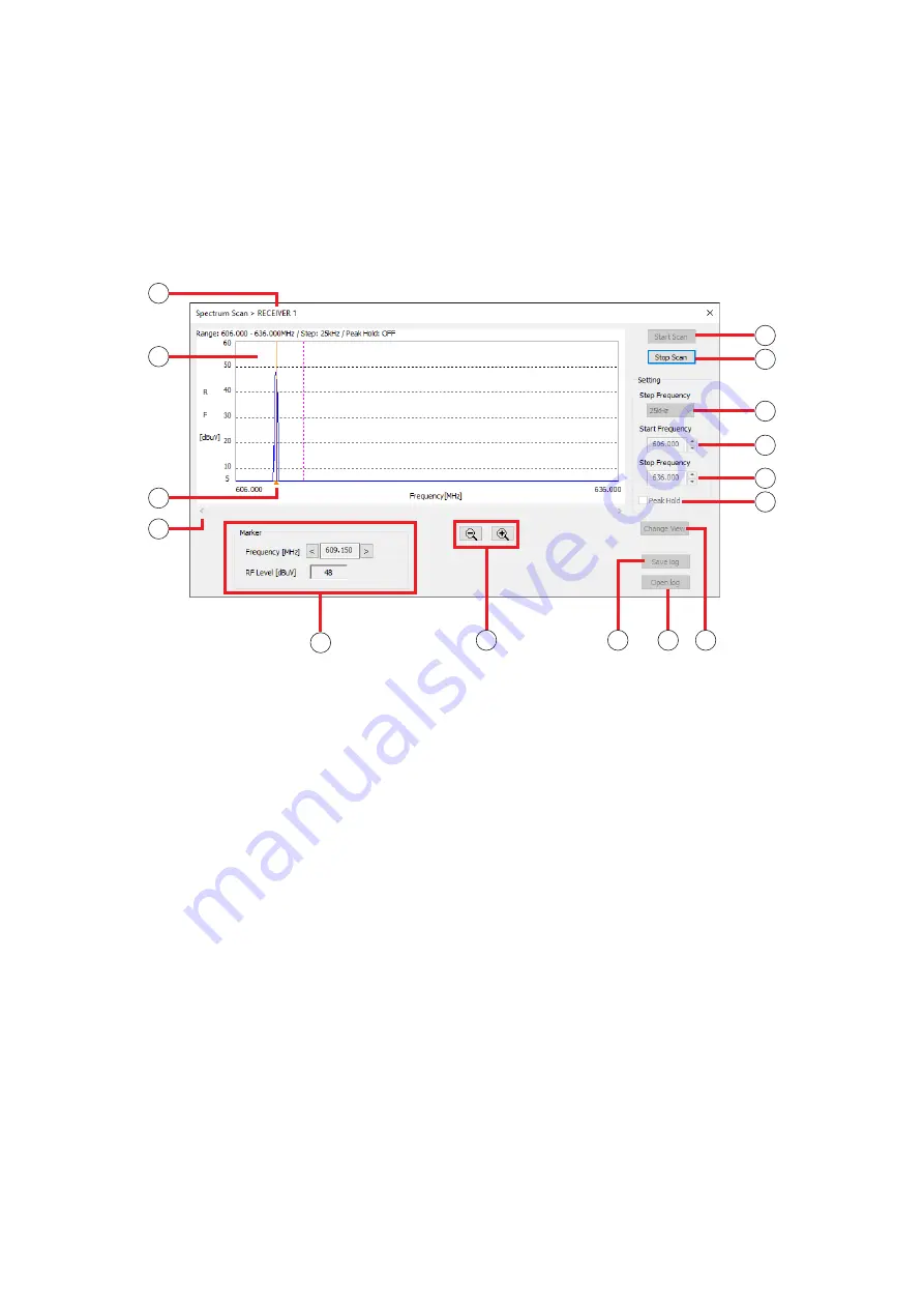
9.1. Spectrum Scan Screen

5

6

7

9

3

4

8

10

11

12

13

14 15

1

2

 1. No.

Displays the receiver’s number.

 2. Scan result display

Shows the channels in the horizontal axis and 

the reception level on the vertical axis as a 

graph.

 3. Marker

Clicking or dragging the graph on the screen will 

show the frequency and reception level on the 

Marker display (11).

 4. Scroll button

Scrolls the graph in the horizontal direction.

 5. Start Scan button

Starts scanning. Scanning will continue until the 

Scan Stop button is clicked.

After 7 days (168 hours), the recording will be 

forced to end.

 6. Stop Scan button

Stops scanning.

 7. Step Frequency

Selects the frequency interval from “25 kHz” or 

“125 kHz.”

 8. Start Frequency

Selects the Min. frequency for scanning.

 9. Stop Frequency

Selects the Max. frequency for scanning.

 10. peak hold function ON/OFF

Sets the display when the same frequency is 

repeatedly scanned.

Clicking the check box will turn the Peak Hold 

function ON, and unclicking it will turn the 

function OFF.

ON  :  Displays the higher reception level results 

by comparing the newest results with the 

past results.

OFF :  Overwrites the graph with the newest 

results.

 11.  Marker  display

Displays the frequency and reception level of the 

marker. 

Clicking the right or left “Frequency” button will 

change the marker location. 

Marker (3) will move along with the frequency.

Содержание WT-D5800

Страница 1: ...tal Wireless Microphone System WT D5800 Maintenance Software Thank you for purchasing TOA s digital wireless microphone system Please carefully follow the instructions in this manual to ensure long tr...

Страница 2: ...Scan Screen 11 6 2 How to Use Channel Scan Function 12 7 SYSTEM STATUS DISPLAY 14 7 1 Receiver Display 14 7 2 When There is No Sound or the Sound is Disrupted 15 7 3 Checking the Signal Status by Reco...

Страница 3: ...r or greater Free hard disk space 200 MB or greater USB USB 2 0 Software requirements OS Windows 7 SP1 32 64 bit Windows 8 1 32 64 bit Windows 10 32 64 bit Note Windows is the registered trademark of...

Страница 4: ...configuration is shown below The Log Files created by this software will be stored in the data folder shown below C ProgramData TOA WT D5800 log Installation folder WT D5800_software exe Execution pro...

Страница 5: ...Internet connecting WT D5800 with the PC will automatically take you to the Windows Update Website and the USB driver required for WT D5800 will be automatically installed on the PC The following scr...

Страница 6: ...on the Windows icon on the lower left corner of the screen to switch it to the Start screen 2 Click on the search icon on the upper right corner of the screen to pull up the search window 3 Enter dev...

Страница 7: ...t using the USB hub Use USB 2 0 A connector pair B connector type Use USB hubs that fit the shape of the connectors Example for connecting 16 receivers Connect the PC with each WT D5800 Digital Wirele...

Страница 8: ...the USB cable and start connecting Once connecting starts the button will be switched to the Disconnect button Clicking the Disconnect button will stop the connection to the receiver Once connecting s...

Страница 9: ...See p 18 Convert to Text Opens the screen where the log files are converted into text See p 19 Open Log Folder Opens the data folder in Explorer See p 4 Walk Test Log Records the reception status log...

Страница 10: ...e PC 2 Walk Test button Used to conduct the Walk Test See p 20 3 Channel Scan button Used to check unused channels See p 11 CHANNEL SCAN 4 Spectrum Scan button Used to check interference See p 24 COND...

Страница 11: ...1 Channel Scan Screen 1 No Displays the receiver s number 2 Scan result display Shows the channels in the horizontal axis and the reception level on the vertical axis as a graph 3 Marker Clicking or...

Страница 12: ...re shown Step 1 Turn off all the microphone switches Step 2 Select a receiver that is connected from the list on the main screen and click on the Channel Scan button Main Screen 2 Displays the Channel...

Страница 13: ...tion levels can be considered available Step 7 Click on the Stop Scan button Channel Scan will stop Step 8 Make a channel plan according to the results The channels with higher reception are considere...

Страница 14: ...etting 6 Code Displays the assigned Code number when the Encryption setting is OFF 7 FBS Displays the ON OFF status of the FBS setting 8 EQ Displays the status of the EQ setting 9 Status Displays the...

Страница 15: ...rrect setting See Antenna instruction manual The receiver s reception indicators light red The Encryption setting or the code setting does not match even though the banks and channels of the microphon...

Страница 16: ...e signal that the receiver is receiving is not strong enough This is not shown by default Encryption setting ON OFF status ID setting and code setting 5 Data Error bluish green Shows the data error wh...

Страница 17: ...right corner on the main screen during recording Notes Do not turn off or disconnect the receiver while the Background Log is being recorded This will prevent the Background log from being stored Rest...

Страница 18: ...he file name Step 1 Select Log Background Log View Log Data from the menu The Background Log screen will be displayed Step 2 Click the Open Log button Step 3 Select a Log File The selected log data wi...

Страница 19: ...older p 4 See p 4 for the file name Step 1 Select Log Background Log Convert to Text from the menu Opens the screen where the log files are converted into text Step 2 Select a log file and click on th...

Страница 20: ...is receiving signals from the microphone and can output sound Sync Error can occur when the settings of the receiver and the microphone do not match or the signal that the receiver is receiving is no...

Страница 21: ...lts of the Walk Test in a file The log file will be stored in the data folder p 4 See p 4 for the file name 14 Open Log button Used to open the screen of the past Walk Test results Walk Test Log scree...

Страница 22: ...will be forced to end Step 8 Click on the Save Log button when the result of the Walk Test needs to be saved as log data The log file will be stored in the data folder p 4 See p 4 for the file name S...

Страница 23: ...y the log data to be displayed The log file will be stored in the data folder p 4 See p 4 for the file name The Walk Test Log will be displayed File name Except that the file name is displayed the con...

Страница 24: ...uency and reception level on the Marker display 11 4 Scroll button Scrolls the graph in the horizontal direction 5 Start Scan button Starts scanning Scanning will continue until the Scan Stop button i...

Страница 25: ...result Spectrum Scan Log screen Spectrum Scan log files will be displayed for selection by clicking this button 15 Change View button Clicking the Change View button will change the horizontal axis t...

Страница 26: ...the Stop Scan button Stops the Spectrum Scan Note After 7 days 168 hours the recording will be forced to end Step 7 Click on the Save Log button when the result of the Spectrum Scan needs to be saved...

Страница 27: ...file will be stored in the data folder p 4 See p 4 for the file name Displays the Spectrum Scan Log screen File name 3 3 Tip Clicking the Change View button will change the horizontal axis to show ti...

Страница 28: ...trol acoustic feedback dynamically When the setting is OFF the parameters for the FBS filter will not be set automatically and the feedback will not be controlled dynamically When the function is turn...

Страница 29: ...01703 11 STOPPING CONNECTION WITH RECEIVERS Clicking the Disconnect button on the main screen will stop the connection to the receivers When the connection is stopped the information on the receiver d...

Отзывы: