


3. Installation
Unpacking and Inspection
Upon receiving the AX-1000A, please inspect it for any shipping damage. If damage is found, notify the carrier
immediately.
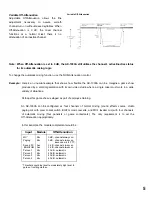
Rack Mounting
The AX-1000A requires 3-unit size. Mounting
brackets are provided. Remove the four
screws securing the case at the left and right
front. Attach the rack mounting brackets. Be
certain to only use the screws that are
included on the AX-1000A unit.
Note:
Allow adequate ventilation: do not block the vents in the cover. Do not locate the AX-1000A :
In unventilated areas.
In an area subject to heavy vibration.
In an area with a high ambient temperature,
or immediately adjacent to equipment which
generates large amounts of heat.
Where it is exposed to direct sunlight.
In a dusty or extremely humid area.
Caution :
There are no user-serviceable parts inside. Never remove the cover, or you run the risk of a fatal
electric shock.
4. Input Signal Flow
Since the AX-1000A has eight input ports for 900 Series plug-in modules, it is completely flexible. Requirements
often vary from installation to installation, and the AX-1000A can be configured exactly to suit each one. In order to
change a given channel's function, simply specify the proper 900 Series input module. The signal flow from the
output of the module(s) is the same for every channel. See Figure 1.
This simplified 'map' of the signal flow does not represent the actual circuitry, only the stages of processing
that occur. Functions that occur after the signals reach the Mixing Bus have been omitted for clarity.
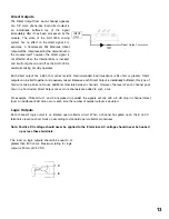
External/Internal Mute buses :
The AX-1000A has two Mute buses,
External Mute Bus
and the
AX-1000A Internal Mute Bus.
Each one
can operate independently, and each one operates at a different stage of the signal chain. Configuring
mutes is explained in detail, below.
9
Содержание AX-1000A
Страница 23: ...18 Block Diagram 23...
Страница 28: ...TOA Corporation Printed in Japan 133 12 157 10...


