5
The pipeline where the valve is fitted should be arranged in such a way that
the valve body is not subjected to any bending or stretching forces.
Bolted joints on the pipeline must not cause additional stress resulting from
excessive tightening, and fastener materials must comply with the working
conditions of the plant,
・
The valve stem should be protected during pipeline painting.
・
The valve can be installed in any position, however it is recommended to install it
with the handwheel upwards.
Take note of the medium flow direction, marked with an arrow on the body.
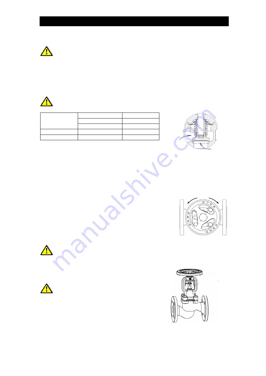
Flow direction is established by the followings rules:
BE8H-16 / BE8H-25
BE8H-40
Stop valve
Stop valve
PN16 – PN25
PN40
Under the disc
DN15 – DN150
DN15 – DN100
On the disc
DN200 DN125
–
DN150
・
Before plant startup, especially after repairs are
carried out, flush out the pipeline through the fully
open valve, in order to discharge solid particles or
Flow under the
disc
Flow on the
disc
welding splinters which may be harmful for sealing surfaces.
・
A strainer (wire mesh filter) installed before the valve increases the certainty of
correct operation.
8. Maintenance
open
shut off
During maintenance the following rules should be observed:
・
Startup process – Sudden changes of pressure and
temperature should be avoided when starting the plant.
・
The valve is closed by turning the handwheel clockwise
when looking down from above the handwheel (according
to the arrow direction marked on the handwheel).
・
The valve is opened by turning the handwheel
counter-clockwise.
Do not use any additional lever when turning the handwheel
・
The performance of fitted valves can be checked by repeated closing and opening.
・
If leakage occurs from the valve stem, it is necessary
to tighten gland nut compressing the gland seal with
moderate force until the leakage stops.
Tighten the nut
Tighten the nut
Leakage on the gland means that the bellows
has been damaged.
The upper part of the valve should be
replaced immediately
TEG-BE8H-M-00 20 August 2013


