
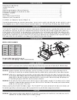
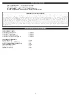

XCHANGER OPERATION BASED ON AIR CHANGES PER HOUR
This method of operation can be used to supplement or provide for guaranteed air change rates. Table 1 shows the constant Cubic
Feet Per Minute (CFM) of air necessary to produce the desired Air Change Per Hour rate (ACH), assuming natural infiltration of out-
side air at a rate of .10 ACH. Square footage is determined by calculating the finished living space of the house. Garages and crawl
space should not be included. The constant CFM figures shown assume that the living space has standard 8 foot ceilings.
1. Determine square footage of house living space on left hand column.
2. Pick desired air change rate from top row.
3. Locate intersection of these points to determine constant CFM that should be obtained to meet desired ACH.
The X
CHANGE
R
TM
will provide 180 CFM with both fans and 90 CFM with one fan operating. Where the CFM delivery of the X
CHANG-
E
R
TM
exceeds that listed in Table 1, a standard plug-in timer can be set so the X
CHANGE
R
TM
is cycled to obtain the
desired ACH or Tjernlund’s optional SCP speed control may be used.
EXAMPLE
3000 square feet of living space
.2 ACH desired ventilation rate equals 40 CFM
X
CHANGE
R
TM
capacity of 90 CFM (with one fan running)
In this example the plug-in timer may be set so that the X
CHANGE
R
TM
operates for one half hour straight each hour or two fifteen
minute periods each hour.
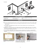
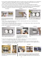
RECOMMENDED INSTALLATION LOCATION
The X
CHANGE
R
TM
may be mounted anywhere in the house. Mount in a location where it is accessible for reversing fans seasonally or
for maintenance.
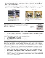
WARNING:
Do not exhaust air from mechanical room unless makeup air is also supplied or equipment in mechanical room is sealed
combustion. Carbon monoxide poisoning may result. Use the optional DT2-6 6” duct take-off kit so exhaust can be
removed from outside the mechanical room if necessary.
It is required that the X
CHANGE
R
TM
be installed in a location where it will not be directed at the occupants. Do not discharge intake air
onto water pipes or other equipment which may be affected by temperature extremes.
Do not terminate adjacent to thermostat. Outside temperatures can disrupt normal thermostat operation.
Do not terminate within three feet from a barometric draft control or intake grille of a heating appliance.
XCHANGER HOOD TERMINATION CLEARANCES
Install X
CHANGE
R
TM
in accordance with BOCA national Mechanical Codes M-306.1 and M-306.1.1 as follows, (See Diagram A).
M-306.1 LOCATION:
Outside air exhaust and intake openings shall be located a minimum of 10 feet (3048mm) from lot lines or build-
ings on the same lot. When openings front on a street or public way, the distance shall be measured to the centerline of the street or
public way.
M-306.1.1 INTAKE OPENINGS:
Outside air intake openings shall be located a minimum of 10 feet (3048mm) from any hazard or
noxious contaminant such as vents, chimneys, plumbing vents, streets, alleys, parking lots and loading docks. When a source conta-
minant is located within 10 feet (3048mm) of an intake opening, such opening shall be located a minimum of 2 feet (610mm) below
the contaminant source.
IN ADDITION TO THESE CODES THE MANUFACTURER RECOMMENDS THAT:
• The X
CHANGE
R
TM
hood should be a minimum of 1 foot above grade or anticipated snow line.
• The X
CHANGE
R
TM
hood should be a minimum of 3 feet from an inside corner of the building.
3
TABLE 1


