Everything Needed to Conform
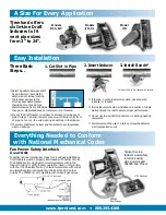
Easy Installation
www.tjernlund.com • 800.255.4208
A Size For Every Application
Models
DJ-3, D-3
Models
I, IL, XL
Model
HD
1. Cut Slot in Pipe
2. Insert Inducer
3. Install Bands*
■
Select a position between draft
hood, diverter or barometric
damper and chimney, locating
the Inducer as close to the
chimney as possible. Inducer
should be mounted 2-3 pipe
diameters away from a directional
change, i.e. elbows and tees, so turbulence is not created.
■
Mount the Draft Inducer on vertical, horizontal or inclined vent
pipe. If used on a horizontal vent pipe, mount Inducer on bottom
of pipe, not on top, to avoid creating a heat trap in the Inducer.
■
The motor shaft must be level and horizontal to avoid excessive
wear on bearing.
Three Basic
Steps...
Typical In-Line
Inducer and safety
interlock using
UC1 Control and
PS1505 Fan Prover
Tjernlund offers
six In-Line Draft
Inducers to fit
vent pipe sizes
from 3" to 24".
UC1 Control
PS1505
Fan Prover
* Models DJ-3 & D-3 fasten with screws.
■
If change in vent pipe size is required, use a tapered
increaser or reducer.
■
In-Line Inducers should be installed on a section of single
wall vent pipe in order to assure proper performance.
■
Do not use In-Line Draft Inducers on condensing heating
equipment.
■
We recommend the use of a carbon monoxide detector
in all mechanical rooms.
Fan Prover Safety Interlock
Model PS1505
To satisfy national mechanical codes for oil and gas installations,
Draft Inducers must be properly interlocked with burner circuits.
The PS1505 Fan Proving Switch monitors pressure within the
Inducer housing to verify Inducer operation. Used in conjunction
with the UC1 Universal Control, it assures compliance with codes
and simplifies electrical interlock with all 24 /115 VAC burner
circuits. The PS1505 is not compatible with millivolt gas valves.
with National Mechanical Codes
Chimney


