
© Titan Tool Inc. All rights reserved.
27
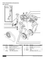
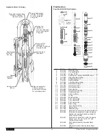
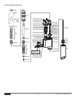
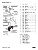
Item Part #
Description
Quantity
1
143-019
Retaining ring ...........................................1
2
143-120
Connecting pin..........................................1
3
145-031
O-ring,
PTFE
............................................2
4
138-153
Packing set, leather/UHMWPE/steel
........2
5
142-004
Upper packing spring................................1
6
144-832
Pump cylinder ...........................................1
7
144-117
Displacement rod......................................1
8
138-001
Spring retainer ..........................................1
9
142-003
Lower packing spring................................1
10
451-085
Outlet valve cage ......................................1
11
138-225
Outlet valve ball ........................................1
12
600-301
Hex screw
.................................................4
13
600-302
Washer .....................................................4
14
600-303
Screw ........................................................1
15
600-304
Pressure plate ..........................................1
16
600-305
Plug plate..................................................1
17
600-306
O-ring ........................................................2
18
600-307
Sealing ring...............................................1
19
600-308
Inlet valve cage.........................................1
20
600-309
Pressure spring ........................................1
21
600-310
Inlet valve ball ...........................................1
22
600-311
Inlet valve seat..........................................1
23
600-312
Grooved pin ..............................................1
24
600-313
Head cap screw ........................................1
25
600-314
O-ring ........................................................1
26
600-315
Plug ..........................................................1
27
600-316
Cap plug ...................................................1
28
600-317
Cleanout adapter ......................................1
29
600-318
O-ring ........................................................1
30
600-320
Outlet valve assembly ..............................1
31
600-321
Cap nut M 6 ..............................................2
32
600-322
Disk spring ................................................4
33
600-323
Rod connector ..........................................1
34
600-324
Hexagon nut M 6
......................................1
35
600-325
Flat screw .................................................1
36
9923504 Disk spring ................................................1
37
600-327
Packing stack ...........................................1
38
600-357
Rod housing assembly .............................1
39
600-328
Retaining ring ...........................................1
40
600-330
O-ring 21 x 2
.............................................1
41
600-331
O-ring 50 x 1.78
........................................1
42
600-332
Groove nut ................................................1
43
600-333
Inlet valve housing ....................................1
44
600-334
O-ring 47 x 2.5
..........................................1
45
600-335
Valve rod ..................................................1
46
600-336
Washer .....................................................1
47
600-337
Shovel valve plate ....................................1
48
600-338
Shovel valve .............................................1
49
600-339
Suction tube..............................................1
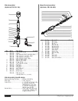
600-300
Shovel valve assembly
(includes items 11 – 46)
600-405
Shovel valve service kit, minor
(includes items 1, 3, 4, 10, 11, 17, 18, 21,
36, 37, 41, and and Loctite P/N 426-051)
600-406
Shovel valve service kit, major
(includes items 6, 7, and fluid section
service kit, minor P/N 600-405)
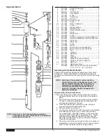
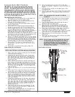
Servicing the PowrTex 6900 SF Fluid Section
IMPORTaNT: use of non-Titan service parts may void
warranty. ask for original parts made by Titan for best
services. This pump should receive a routine servicing
after approximately 1,000 hours of use. Earlier servicing is
required if there is excessive leakage from the top packing
or if pump strokes become faster on one stroke or the other.
The use of Titan Piston Lube (P/N 314-480) is recommended
as an upper packing lubricant. Do not substitute oil, water, or
solvent for an upper packing lubricant.
Disassembling the Fluid Section
1. Loosen the shovel valve groove nut (39) by turning it
clockwise using a spanner wrench.
2. Slide the retaining ring (1) up with a small screwdriver,
and push out the connecting pin (2) that connects the
displacement rod (7) to the hydraulic piston rod.
3. Unscrew the shovel valve assembly from the pump
cylinder (6).
4. Pull down the shovel valve assembly and remove the
entire displacement rod assembly (7) with the shovel valve
assembly from the pump cylinder (6).
5. Using two wrenches, remove the outlet valve assembly
(30) from the shovel valve rod connector (33). Set aside
the shovel valve assembly.
6. Using a strap wrench, remove the pump cylinder (6) from
the motor pump block.
7. Remove the
PTFE
o-ring (3), upper packing spring (5),
and upper packing set (4) from the motor/pump block.
8. Hold the displacement rod (7) in a vise by the flats at
the top of the displacement rod. Remove the outlet
valve assembly (30) with a wrench while holding the
displacement rod horizontal with a wooden support, if
necessary. Remove the outlet valve ball (11), outlet valve
cage (10), lower packing set (4), lower packing spring (9),
and spring retainer (8).
Reassembling the Fluid Section
1. After soaking the new leather packings in oil (preferably
linseed oil), reassemble the lower packing set (4). Place
the set onto the outlet valve assembly (30) with the peak
of the “V” packings pointing down toward the hex on the
outlet valve assembly.
NOTE: all leather packings must be soaked in oil for
15–20 minutes before installation. Soaking the
packings too long will cause the packings to
swell and create difficulty during reassembly.
2. Insert the outlet valve cage (10) and new outlet valve ball
(11) into the displacement rod (7).
3. Clean the threads on the outlet valve assembly (30) and
coat the threads with blue Loctite #242. Make sure the
Loctite is only on the threads.
4. Place the lower packing spring (9) onto the outlet valve
assembly (30) followed by the spring retainer (8).
5. Screw the displacement rod (7) and the outlet valve
assembly (30) together. Tighten in a vise to 900 in./lbs.
(75 ft./lbs.).
6. Insert the
PTFE
o-ring (3) into the upper grove of the
motor/pump block.
7. Insert the upper packing set (4) into the motor/pump block
with the peak of the “V” packings pointing up toward the
motor.
8. Place the upper packing spring (5) into the motor/pump
block with the small tapered end facing up toward the
motor/pump block.
9. Thread the short threads of the pump cylinder (6) into the
motor/pump block and tighten with a strap wrench.
10. Make sure the retaining ring (36) is in the groove above
the threads on the pump cylinder.
11. Locate the shovel valve assembly and thread the outlet
valve housing (30) onto the shovel valve rod connector
(33). Tighten securely using two wrenches.
12. Insert the displacement rod (7) with the shovel valve
assembly up through the pump cylinder and the upper
packings in the motor/pump block.
13. Thread the shovel valve assembly onto the pump cylinder
(6) until it stops and then back off until it reaches the
desired position.
14. Align the holes in the displacement rod (7) and the
hydraulic piston rod and insert the connecting pin (2).
Replace the retaining ring (1) over the connecting pin.
15. Apply a small amount of blue Loctite #242 to the inside
threads of the shovel valve groove nut (39). Tighten the
groove nut securely by turning it counterclockwise using a
spanner wrench.
Содержание SPEEFLO PowrTex 12000 SV
Страница 35: ...Titan Tool Inc All rights reserved 35 Notes...


