background image

18

© Titan Tool Inc.  All rights reserved.

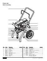
Parts List 

Main Assembly

1

5

6

2

12

13

4

8

7

9

10

11

3

14

15

17

18

19
20

16

Item

Part #

Description

Quantity

1

800-600

Cart assembly.............................................1

2

----------

Drive assembly ...........................................1

3

761-178

Screw..........................................................4

4

800-324

Pail hook .....................................................1

5

763-551

Lock washer................................................2

6

858-625

Screw..........................................................2

7

800-328

Knock-off nut...............................................1

8

800-300

Fluid section assembly ...............................1

9

451-241

Siphon tube.................................................1

10

730-334

Hose clamp.................................................1

11

710-046

Inlet screen .................................................1

12

800-268

Fitting ..........................................................1

Item

Part #

Description

Quantity

13

800-904

Return hose ................................................1

14

800-900

Filter assembly............................................1

15

812-003

Outlet fitting.................................................1

16

800-915

PRIME/SPRAY valve assembly..................1

17

800-269

Fitting ..........................................................1

18

800-267

Fitting (high rider) .......................................1

800-268

Fitting (low rider, not shown) ......................1

19

860-002

Lock washer................................................2

20

860-535

Screw..........................................................2

21

800-266

Hose (not shown) .......................................1

22

818-002

Elbow, 90º, return hose
(low rider, not shown) .................................1

Содержание 800-130-ce

Страница 1: ...ual For professional use only NOTE This manual contains important warnings and instructions Please read and retain for reference International Model NOTE This manual contains important warnings and in...

Страница 2: ...ular cleaning and maintenance of the unit must be strictly observed Before any work is done on the unit or for every break in work the following rules must be observed 1 Release the pressure from the...

Страница 3: ...e A leak is capable of injecting material into the skin Inspect the paint hose before each use DO NOT TREAT AN INJECTION INJURY AS A SIMPLE CUT Injection can lead to amputation See a physician immedia...

Страница 4: ...new it is shipped with test fluid in the fluid section to prevent corrosion during shipment and storage This fluid must be thoroughly cleaned out of the system with mineral spirits before you begin sp...

Страница 5: ...a static electric discharge which may cause a fire 11 Trigger the gun into the metal waste container until all air and solvent is flushed from the spray hose and paint is flowing freely from the gun W...

Страница 6: ...to remove any pressure that may still be in the hose 6 Lock the gun by turning the gun trigger lock to the locked position 7 Move the PRIME SPRAY valve down to the PRIME position Spraying POSSIBLE IN...

Страница 7: ...Pressure Relief Procedure found in the Operation section of this manual 2 Remove the gun tip and tip guard and clean with a brush using the appropriate solvent WARNING CAUTION WARNING Good spray patt...

Страница 8: ...s Lift the electronic cover off of the electronic control assembly on the motor WARNING CAUTION WARNING 8 Titan Tool Inc All rights reserved 6 At the electronic control assembly a Disconnect the white...

Страница 9: ...e transducer wire out through the mounting plate 7 Slide the grommet off of the old transducer and onto the new transducer 8 Thread the new transducer wire through the mounting plate and up to the ele...

Страница 10: ...alve Ball Outlet Valve Cage Outlet Valve Seal Piston Rod Upper Housing Lower Housing Foot Valve Housing Black O Ring O ring White Back Up Ring Foot Valve Seat Foot Valve Ball Foot Valve Cage Lower Hou...

Страница 11: ...ing and secure in position using the four front cover screws NOTE For low rider units make sure the hose does not touch the cart frame If it does reposition the nipple by turning the upper housing unt...

Страница 12: ...wing the Servicing the Fluid Section procedure in the Maintenance section of this manual 10 Take unit to a Titan authorized service center 1 Repack the pump following the Servicing the Fluid Section p...

Страница 13: ...a minimum of 5m 50 x 10mm 1 4 grounded textile braid airless paint spray hose 2 Replace the spray tip following the instructions that came with the spray gun 3 Rotate the pressure control knob counter...

Страница 14: ...auds surfaces chaudes etc 5 Attention Risque de blessure par injection Ne jamais pointer le pistolet vers vous m mes ou une personne quelconque Ne jamais mettre les doigts ou la main dans le jet de pu...

Страница 15: ...onsulter imm diatement un m decin DANGER EXPLOSION OU INCENDIE Les vapeurs de solvant ou de peinture sont explosives et inflammables et peuvent causer des dommages mat riels et ou corporels s rieux ME...

Страница 16: ...de prevenci n de explosiones 4 Nunca operar cerca de fuentes de combusti n v gr llamas abiertas cigarrillos cigarros y pipas chispas alambres al rojo vivo superficies calientes etc 5 Atenci n Riesgo d...

Страница 17: ...CION COMO UN SIMPLE CORTE La inyecci n puede conducir a la amputaci n Consultar a un m dico inmediatamente Espa ol PELIGRO EXPLOSION O INCENDIO Los gases de solventes y pintura pueden explotar o prend...

Страница 18: ...800 300 Fluid section assembly 1 9 451 241 Siphon tube 1 10 730 334 Hose clamp 1 11 710 046 Inlet screen 1 12 800 268 Fitting 1 Item Part Description Quantity 13 800 904 Return hose 1 14 800 900 Filt...

Страница 19: ...scription Quantity 23 800 076 Screw 1 24 800 274 Potentiometer mounting plate 1 25 700 176 Nut 1 26 700 175 Cap 1 27 700 159 Pressure control knob 1 28 800 277 Potentiometer 1 29 800 203 Screw 1 30 70...

Страница 20: ...packing with the side that has the o ring closest to the top of the packing facing up Install upper packing with raised lip facing down Raised Lip 22 Closer Top NOTE When repacking the fluid section...

Страница 21: ...acking kit includes items 2 3 5 8 11 13 14 18 20 and tool High Rider Cart P N 800 600 Item Part Description Quantity 1 800 280 Handle includes items 2 5 11 and 12 1 2 590 508 Roll pin 2 3 590 507 Snap...

Страница 22: ...spacer 4 14 800 593 Wheel 2 15 704 355 Cap 2 16 800 112 Cart weldment includes items 8 and 10 1 Siphon Set low rider 1 2 3 4 5 6 Item Part Description Quantity 1 800 903 Return hose 1 2 710 203 Sipho...

Страница 23: ...commended maximum tip size Electronic Control Assy Indicator Lights Assembly 800 278 BLACK RED WHITE BLACK RED WHITE BLUE YELLOW GRAY PURPLE Transducer 800 449 BLACK WHITE WHITE BLUE BROWN BLACK BLACK...

Страница 24: ...be returned to an authorized Titan sales service outlet All transportation charges including return to the factory if necessary are to be borne and prepaid by the End User Repaired or replaced equipme...

Отзывы: