© Titan Tool Inc. All rights reserved.
19
Before proceeding, follow the “Pressure Relief Procedure”
in the Operation section of this manual. Additionally,
follow all other warnings to reduce the risk of an injection
injury, injury from moving parts or electric shock. Always
unplug the sprayer before servicing!
Replacing the Gear
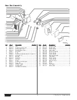
1. Remove the safety plate (33).
2. Remove the outlet mounting bolt from the rear of the
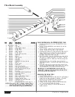
pump (refer to the Filter Block Assembly parts list).
3. Remove the head cap screws with a 3/16" hex wrench.
(refer to the Fluid Section Assembly parts list).
4. Slide the fluid section from the crank and slide connecting
rod assembly (refer to the Fluid Section Assembly parts
list). If the fluid section will not slide off, use a screwdriver
to pry the fluid section down, then slide it off.
5. Remove the front plate (32).
6. Using a 3/16" hex wrench, remove the four screws (30)
that secure the pump housing (29) to the gearbox housing
(22).
7. Slide the pump housing (29) off the gear box housing
(22).
8. Inspect the gears beginning with the crankshaft (26),
followed by the output pinion gear (25)and the pinion gear
(21).
9. Inspect the pinion gear (21) on the motor by removing the
motor as described in the “Replacing the Motor”
procedure.
10. Reassemble by reversing the above order. When
reassembling, make sure that all washers are in place and
that the gears and bearing are properly lubricated.
11. Grease the crankshaft (26) every 100 hours. The grease
fitting is located under the front plate (32).
12. Grease the crank and slide connecting rod assembly
every 100 hours (refer to the Fluid Section Assembly parts
list). The grease fitting is located on the crank and slide
connecting rod assembly under the front plate (32).
Replacing the ON/OFF Switch
1. Remove the four screws (12) that secure the pressure
control board (13) to the gear box housing. Remove the
pressure control board.
2. Disconnect the two black wires from the ON/OFF Switch
(15).
3. Using a wrench, remove the rubber boot (19) and the
ON/OFF plate (18).
4. Remove the ON/OFF switch (15).
5. Install a new ON/OFF switch (15) and reattach the
ON/OFF plate (18) and rubber boot (19). Tighten securely.
6. Reconnect the two black wires to the new ON/OFF Switch
(15).
7. Reinstall the pressure control board (13) and secure in
position using the four screws (12).
Replacing the Power Cord
1. Remove the four screws (12) that secure the pressure
control board (13) to the gear box housing. Remove the
pressure control board.
2. Disconnect the power cord (7) from the ON/OFF switch
(15), the pressure control board (13), and the grounding
screw (refer to the electrical schematic).
3. Loosen the cord grip housing (11) and remove the power
cord (7).
4. Install the new cord in the reverse order of disassembly.
5. Reinstall the pressure control board (13) and secure in
position using the four screws (12).
WARNING
Pressure Switch Replacement
1. Remove old pressure switch. Be sure all loose parts are
removed from the electrical box in the gear box housing
(22).
2. Install the transducer assembly (17) with o-rings in place.
Then press the assembly securely into the filter block. It
is recommended that you replace the polyethylene gasket
that is between the pump and the filter block.
3. Reattach the filter block by guiding the transducer wires
through the bottom hole of the electrical box in the gear
box housing (22). Reinstall the two original bolts that
mount the filter block to the pump. Be sure to tighten
them evenly.
5. When installing the plastic potentiometer mount (4), from
the top of the electrical box, be sure the stop (raised
portion of the mount) is closest to the opening of the
electrical box. Square up the mount to the opening. Use
a rubber mallet to press the mount onto the pump, making
it flush. Loctite is supplied for mounting.
6. Put the potentiometer shaft (16), through the upper hole
in the electrical box, from the inside. The wires on the
potentiometer should come out of the box. Turn the
potentiometer, clockwise or counterclockwise until it finds
the locating hole and stops turning. Install the rotary
switch seal (3), onto the shaft of the potentiometer. Use a
needle nose pliers to start the nut, and with a 1/2” socket
1/4” drive, tighten to a torque of 4 inch-lbs.
7. Turn the potentiometer shaft (16) clockwise until it stops.
8. Loosen the nut on pressure control knob (2), and install
onto the shaft of the potentiometer (16) with the pointer
pointing away from the opening of the electrical box.
9. Hand tighten the nut onto the pressure control knob (2)
and turn the knob clockwise until it hits the stop. With a
5/16” socket, tighten the nut onto the knob to 2 inch-lbs.
Install the plastic cap (1) onto the top of the knob.
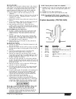
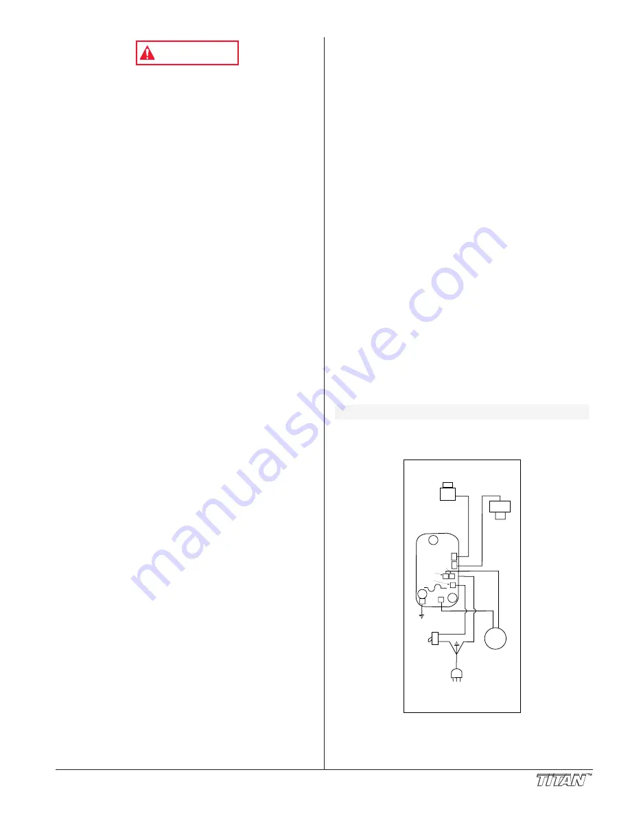
Electrical Schematic
TRANSDUCER
700-197
POTENTIOMETER
700-158
PRESSURE
CONTROL
BOARD
440HP-- 700-161
447HPX -- 700-162
SWITCH
MOTOR
PLUG
BLACK
BLACK
WHITE
WHITE
J5
NEUT
J6
SWITCH
J7
MOTOR
J8
GND
J3
J2
J4
MOTOR
ELECTRICAL CONTROL ASSEMBLY
110V -- 440; 550
NOTE: Do not over-tighten the nut on the potentiometer.


