background image


3

 CONTENTS

IMPACT 1040T

SAFETY REGULATIONS FOR AIRLESS

 SPRAYING ______________________________ 4

1.1  Explanation of symbols used _____________________4
1.2  Grounding instructions _________________________4
1.3  Safety hazards ________________________________5

MAIN AREA OF APPLICATION _____________ 8

2.1  Technical data ________________________________8

DESCRIPTION OF UNIT ___________________ 8

3.1  Airless process ________________________________8
3.2  Functioning of the unit _________________________8
3.3  System diagram _______________________________9

4 OPERATION ____________________________ 10

4.1  Using the gun trigger lock ______________________10
4.2 Setup ______________________________________10
4.3  Preparing a new sprayer _______________________11
4.4  Preparing to spray ____________________________12
4.5 Spraying ____________________________________13
4.6  Pressure relief procedure _______________________13
4.7  Control panel indicators _______________________14

SPRAYING TECHNIQUE __________________ 15

5.1  Cleaning a clogged tip _________________________15

6 CLEANUP ______________________________ 16

6.1  Special cleanup instructions for use with
 

flammable solvents ___________________________16

6.2  Cleaning the sprayer __________________________16
6.3  Cleaning the outside of the unit _________________16
6.4  Cleaning the filter screen _______________________17
6.5  Cleaning the spray gun ________________________17
6.6  Cleaning the high pressure filter _________________18

7 TROUBLESHOOTING ____________________ 19

8 SERVICING _____________________________ 20

8.1  General servicing _____________________________20
8.2  High-pressure hose ___________________________20

9 MAINTENANCE _________________________ 20

9.1  PRIME/SPRAY valve ___________________________20
9.2  Inlet and outlet valve __________________________21
9.3  Repacking the fluid section _____________________22
9.4  Replacing the motor __________________________24
9.5  Replacing the gears ___________________________24
9.6  Replacing the transducer ______________________25
9.7  Impact 1040T connection diagram _______________26

WARRANTY _________________________________ 27

SPARE PARTS LISTS __________________________ 80

Spare parts list for main assembly __________________ 80/81
Spare parts list for the fluid section _________________ 82/83
Spare parts list for drive assembly  _________________ 84/85
Spare parts list of filter plug assembly_______________ 86/87
Spare parts list for upright cart ____________________ 88/89

ACCESSORIES ____________________________ 90/91

Содержание 2405360

Страница 1: ...2404439B Doc 11308316 AIRLESS HIGH PRESSURE SPRAYING UNIT GROUPE DE PROJECTION À HAUTE PRESSION AIRLESS EQUIPO DE ALTA PRESIÓN PARA PULVERIZAR EN OPERATING MANUAL 2 F MODE D EMPLOI 28 ES INSTRUCCIONES DE USO 54 OPERATING MANUAL ...

Страница 2: ...Inform the doctor about the coating material or solvent used The operating instructions state that the following points must always be observed before starting up 1 Faulty units must not be used 2 Secure Titan spray gun using the trigger lock on the trigger 3 Ensure that the unit is properly earthed 4 Check allowable operating pressure of high pressure hose and spray gun 5 Check all connections fo...

Страница 3: ... solvents____________________________16 6 2 Cleaning the sprayer___________________________16 6 3 Cleaning the outside of the unit__________________16 6 4 Cleaning the filter screen________________________17 6 5 Cleaning the spray gun_________________________17 6 6 Cleaning the high pressure filter__________________18 7 TROUBLESHOOTING_____________________ 19 8 SERVICING___________________________...

Страница 4: ...product is equipped with a cord having a grounding wire with an appropriate grounding plug The plug must be plugged into an outlet that is properly installed and grounded in accordance with all local codes and ordinances WARNING Improper installation of the grounding plug can result in a risk of electric shock If repair or replacement of the cord or plug is necessary do not connect the green groun...

Страница 5: ...e turnofftheunitand relieve the pressure in accordance with the manufacturer s instructions High pressure spray is able to inject toxins into the body and cause serious bodily injury In the event that injection occurs seek medical attention immediately Check hoses and parts for signs of damage a leak can inject materialintotheskin Inspecthosebeforeeachuse Replace any damaged hoses or parts Only us...

Страница 6: ...wer cords Useextremecautionwhenusingmaterialswithaflashpoint below 100ºF 38ºC Flashpoint is the temperature that a fluid can produce enough vapors to ignite Paint or solvent flowing through the equipment is able to result in static electricity Static electricity creates a risk of fire or explosion in the presence of paint or solvent fumes All parts of the spray system including the pump hose assem...

Страница 7: ... Always wear appropriate gloves eye protection clothing and a respirator or mask when painting Do not operate or spray near children Keep children away from equipment at all times Do not overreach or stand on an unstable support Keep effective footing and balance at all times Stay alert and watch what you are doing Do not operate the unit when fatigued or under the influence of drugs or alcohol Do...

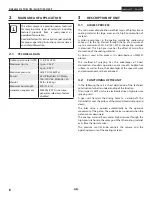
Страница 8: ... pressure of up to a maximum of 221 bar 22 1 MPa the coating material is atomised This high pressure has the effect of micro fine atomisation of the coating material As no air is used in this process it is described as an AIRLESS process This method of spraying has the advantages of finest atomisation cloudless operation and a smooth bubble free surface As well as these the advantages of the speed...

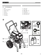
Страница 9: ...tor 2 Pressure control knob 3 ON OFF switch 4 Oiler cap 5 Oiler button 6 Pail bracket 7 Fluid section 8 Siphon tube 9 Return hose 10 PRIME SPRAY valve 11 Outlet fitting 12 Liquid Shield 4 oz 13 Piston Lube 4 oz 10 PRIME SPRAY k p 10 11 5 7 8 9 4 6 1 12 13 3 2 ...

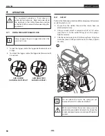
Страница 10: ...LL NOT SPRAY GUN UNLOCKED GUN WILL SPRAY 4 2 SETUP Perform the following procedure before plugging in the power cord of an electric unit 1 Ensure that the siphon tube and the return hose are attached and secure 2 Using a wrench attach a minimum of 50 of 1 4 airless spray hose 1 to the outlet fitting 2 on the sprayer Tighten securely 3 Attach an airless spray gun 3 to the spray hose Using two wrenc...

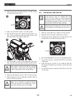
Страница 11: ...ge three wire extension cord with a grounded plug Never remove the third prong or use an adapter 4 3 PREPARING A NEW SPRAYER i If this sprayer is new it is shipped with test fluid in the fluid section to prevent corrosion during shipment and storage This fluid must be thoroughly cleaned out of the system with mineral spirits before you begin spraying Always keep the trigger lock on the spray gun i...

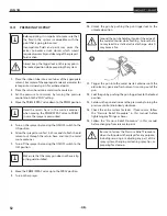
Страница 12: ...rough the return hose and into the metal waste container 7 Turn off the sprayer by moving the ON OFF switch to the OFF position i Make sure that the spray gun does not have a tip or tip guard installed 8 Move the PRIME SPRAY valve up to the SPRAY position 9 Turn on the sprayer 10 Unlock the gun by pushing the gun trigger lock to the unlocked position Ground the gun by holding it against the edge o...

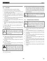
Страница 13: ...spray without the tip guard in place Never trigger the gun unless the tip is in either the spray or the unclog position Always engage the gun trigger lock before removing replacing or cleaning tip 16 Turn on the sprayer 17 Increase the pressure by turning the pressure control knob slowly clockwise and test the spray pattern on a piece of cardboard Adjust the pressure control knob until the spray f...

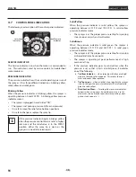
Страница 14: ... worn or the sprayer is in need of service repair Solid Yellow When the pressure indicator is solid yellow the sprayer is operating between 201 PSI and 1900 PSI A solid yellow pressure indicator means The sprayer is at the proper pressure setting for spraying stain lacquer varnish and multi colors Solid Green When the pressure indicator is solid green the sprayer is operating between 1901 PSI and ...

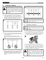
Страница 15: ...ould be moving when the trigger is pulled and released Overlap each stroke by about 30 This will ensure an even coating 25 30 cm 25 30 cm C i If very sharp edges result or if there are streaks in the spray jet increase the operating pressure or dilute the coating material 5 1 CLEANING A CLOGGED TIP i If the spray pattern becomes distorted or stops completely while pulling the trigger perform the s...

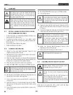
Страница 16: ... to its RAPID CLEAN position 7 Turn on the sprayer by moving the ON OFF switch to the ON position 8 Allow the solvent to circulate through the unit and flush the paint out of the return hose into the metal waste container 9 Turn off the sprayer by moving the ON OFF switch to the OFF position 10 Move the PRIME SPRAY valve up to its SPRAY position 11 Turn on the sprayer Ground the gun by holding it ...

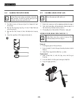
Страница 17: ... spray gun after each use 1 Rinse airless spray gun with an appropriate cleaning agent 2 Clean tip thoroughly with appropriate cleaning agent so that no coating material residue remains 3 Thoroughly clean the outside of the airless spray gun INTAKE FILTER IN AIRLESS SPRAY GUN FIG 11 i Follow these steps if you used an accessory filter sold separately for the spray gun Removal 1 Pull trigger guard ...

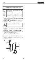
Страница 18: ...e down to its PRIME position 3 Switch the unit OFF Unplug the power plug from the outlet 4 Unscrew the filter housing Fig 12 Item 1 with a strap wrench 5 Pull the filter cartridge 2 from the bearing spring 3 6 Clean all the parts with the corresponding cleaning agent If necessary replace the filter cartridge 7 Check the O ring 4 replace it if necessary 8 Place the bearing ring 5 against the bearin...

Страница 19: ...ition 2 Check the siphon tube siphon assembly connection and tighten or re tape the connection with PTFE tape 3 Remove the pump filter element and clean Remove the inlet screen and clean 4 Remove the siphon tube siphon assembly and clean 1 Replace the spray tip following the instructions that came with the spray gun 2 Replace the spray tip with a tip that has a smaller orifice following the instru...

Страница 20: ...erformed on any electrical components Use an ohmmeter to determine that there is continuity between accessible dead metal parts of the product and the grounding blade of the attachment plug 9 1 PRIME SPRAY VALVE Attention The valve housing 4 should not be repaired If worn it should always be replaced with a new one 1 Use a drift punch of 2 mm to remove the grooved pin Fig 13 Item 1 from the valve ...

Страница 21: ...ve seat 7 and inlet valve ball 8 for wear and replace the parts if necessary If the worn inlet valve seat 7 is unused on one side install it the other way around 1 3 9 7 8 6 5 4 2 9 Carry out installation in the reverse order Lubricate O ring 5 with machine grease and ensure proper seating in the inlet valve housing 2 10 Unscrew lower housing Fig 15 Item 10 with adjusting wrench while holding the ...

Страница 22: ... 3 7 Push the connecting pin 4 out of the extension slider and piston rod and remove the piston rod 5 upper housing 1 8 Placethefluidsectioncylinderuprightinavisebyclamping on the wrench flats Fig 17 Item 6 Attention Do not tighten vice excessively to prevent crushing 9 Using a wrench remove the upper seal retainer 7 10 Slide the piston rod 5 out through the bottom of the upper housing 1 11 Inspec...

Страница 23: ...tension slider insert the connecting pin 4 27 Thread the upper housing 1 into the cylinder 2 turning clockwise 28 Continue to turn the upper housing clockwise until it is flush against the cylinder 29 Replace the cylinder 2 back into the fluid section clamp on the gear housing Make sure to slide the top of the piston rod extension into the T slot on the slider assembly 30 Place the fluid section b...

Страница 24: ...rews 12 15 Place motor controller 11 back into place behind the motor baffle 13 Secure with the two motor controller screws 10 16 Reconnect all wires between the motor 7 and sprayer 17 Place the motor cover 6 back over the motor controller 11 Secure with the two motor cover screws 5 18 Put the belly pan 4 back in place and secure with the three belly pan screws 3 19 Slide the motor shroud 2 over t...

Страница 25: ...om the filter housing 8 Carefully thread the transducer wire out through the mounting plate 8 Slide the grommet 6 off of the old transducer 7 and onto the new transducer 9 Thread the new transducer wire through the mounting plate and back to the motor controller 5 10 Thread the new transducer 7 into the filter housing 8 and tighten securely with a wrench i Make sure the o ring on the transducer is...

Страница 26: ...or Motor controller P N 0552990 P N 805 271A P N 9850936 P N 0522027 P N 0522404 P N 0522210 P N 805 387 P N 0522020 P N 0522024 P N 765 072 Fuse block Fuse Motor Surge suppressor P N 0551972 Fan P N 0552403 Hall sensor from motor P N 800 437 P N 0508579 P N 0522007 L E D Pressure sensor Potentiometer ...

Страница 27: ...tion charges including return to the factory if necessary are to be borne and prepaid by the End User Repaired or replaced equipment will be returned to the End User transportation prepaid THERE IS NO OTHER EXPRESS WARRANTY TITAN HEREBY DISCLAIMS ANY AND ALL IMPLIED WARRANTIES INCLUDING BUT NOT LIMITED TO THOSE OF MERCHANTABILITY AND FITNESS FOR A PARTICULAR PURPOSE TO THE EXTENT PERMITTED BY LAW ...

Страница 28: ...eignez le médecin sur la nature de la peinture ou du solvant utilisés Avant toute mise en service respecter les points suivants conformément aux instructions de service 1 Ne jamais utiliser un équipement défectueux 2 Verrouiller le pistolet Titan par le levier de sécurité à la gâchette 3 Assurer la mise à la terre correcte 4 Vérifier et respecter les pressions admissibles pour le flexible et le pi...

Страница 29: ...vec des solvants inflammables ________42 6 2 Nettoyage du pulvérisateur_____________________42 6 3 Nettoyage extérieur du groupe__________________42 6 4 Filtre d aspiration______________________________43 6 5 Nettoyage du pistolet Airless____________________43 6 6 Nettoyage du filtre haute pression________________44 7 DÉPANNAGE____________________________ 45 8 ENTRETIEN____________________________...

Страница 30: ...urant électrique Le cordon de l appareil est doté d un fil de terre relié à la troisième broche de sa fiche Cette dernière doit être branchée dans une prise correctement câblée et mise à la terre conformément aux codes et règlements locaux MISE EN GARDE Le fait de ne pas brancher correctement la fiche trifilaire de l appareil peut entraîner des risques de choc électrique Si on doit réparer ou remp...

Страница 31: ...érez la pression conformément aux instructions du fabricant La pulvérisation à haute pression peut injecter des toxines dans le corps et causer de graves blessures corporelles Si une telle injection se produisait consultez immédiatement un médecin Vérifiez les tuyaux et les pièces pour détecter des signes d endommagement une fuite peut injecter le produit dans la peau Inspectez le tuyau avant chaq...

Страница 32: ... Évitez de produire des étincelles en connectant et en déconnectant les cordons électriques S entourer de toutes les précautions possibles lorsqu on utilise des produits ayant un point d éclair inférieur à 38 C 100 F Le point d éclair est la température à laquelle le liquidepeutcréersuffisammentdevapeursets enflammer L écoulement de peinture ou de solvant dans l équipement peut produire de l élect...

Страница 33: ...s prescriptions des fabricants au sujet des produits de peinture de nettoyage et des solvants pendant la préparation la mise en oeuvre et le nettoyage du matériel RISQUE GÉNÉRALITÉS peut entraîner des blessures sévères ou des dégâts matériels PRÉVENTION Portez toujours les gants la protection oculaire les vêtements et un respirateur ou masque appropriés quand vous peignez Ne travaillez pas et ne p...

Страница 34: ...re le produit et le refoule sous pression vers la buse En passant par l orifice de la buse avec une pression de maximum 228 bar 22 8 MPa le produit est éclaté en très fines particules Etant donné l absence d air dans ce système il est connu sous le nom AIRLESS sans air Ce procédé de projection comporte les avantages tels que pulvérisation très fine peu de brouillard surfaces lisse sans bulles A pa...

Страница 35: ... pression 3 Communtateur ON OFF 4 Bouchon de graisseur 5 Bouton de graisseur 6 Support de seau 7 Section des liquides 8 Flexible d aspiration 9 Tube de retour 10 Soupape PRIME SPRAY 11 Raccord de flexible 12 Liquid Shield 118 ml 13 Piston Lube 118 ml 10 PRIME SPRAY k p 10 11 5 7 8 9 4 6 1 12 13 3 2 ...

Страница 36: ...AS DÉTENTE DÉBLOQUÉE LE PISTOLET PULVÉRISE 4 2 INSTALLATION On doit procéder aux étapes suivantes avant de brancher le cordon d alimentation de l appareil 1 S assurer que le flexible et le bloc d aspiration soient solidement fixés 2 Fixer un flexible de vaporisation 1 conçu pour les appareils à dépression et mesurant au moins 15 mètres 50 pi au raccord de sortie sur le pulvérisateur Serrez bien 3 ...

Страница 37: ...être trifilaires de calibre 12 et dotées d une fiche à broche de MALT on ne doit jamais retirer cette troisième broche ou utiliser un adaptateur 4 3 PRÉPARATION D UN NOUVEAU VAPORISATEUR i Si cet appareil est neuf il contient encore un liquide d essai mis en usine pour le protéger de la corrosion en cours d expédition ou d entreposage Ce liquide doit être complètement éliminé au moyen d essence mi...

Страница 38: ...en mettant le commutateur à la position OFF i S assurer que l embout ou le protège embout ne soient pas installés 8 Soulever la soupape PRIME SPRAY à la position SPRAY 9 Mettre l appareil en marche 10 Déverrouiller le pistolet en mettant le verrou de détente à la position appropriée On doit mettre le pistolet à la terre en le tenant contre le bord du contenant de purge métallique pendant qu il se ...

Страница 39: ...ives accompagnant ces derniers RISQUES D INJECTION Ne pas vaporiser sans avoir installé le protège embout Ne jamais appuyer sur la détente sans avoir mis l embout en position de vaporisation ou de désobstruction Toujours enclencher le verrou de détente avant de retirer de remplacer ou de nettoyer l embout 16 Mettre l appareil en marche 17 Augmenter la pression en tournant lentement le bouton de ré...

Страница 40: ... est usé ou que le pulvérisateur doit être entretenu réparé Jaune fixe Quand le voyant de pression est jaune fixe le pulvérisateur travaille à une pression comprise entre 201 PSI 14 bar et 1 900 PSI 120 bar Un voyant de pression jaune fixe signifie le pulvérisateur est réglé à la bonne pression pour pulvériser de la teinture de la laque du vernis et du multicolore Vert fixe Quand le voyant de pres...

Страница 41: ...aites chevaucher les passages sur environ 30 pour garantir une couche uniforme 25 30 cm 25 30 cm C i Silesbordsdeprojectionsonttropnetsous ilyades bandes dans le jet il faut soit augmenter la pression de projection soit diluer davantage le produit 5 1 DÉGAGER LA BUSE DE PULVÉRISATION i Si la répartition de votre pulvérisation devient déforméeousilapulvérisationcessecomplètement au cours de la pulv...

Страница 42: ...on pour le rapid clean par pulsations en mettant le bouton de régulation à la position RAPID CLEAN 7 Mettre l appareil en marche en mettant le commutateur à la position ON 8 Laisser le solvant circuler dans l appareil pour évacuer le produit de peinture par le flexible de retour jusqu au contenant de purge 9 Arrêter l appareil en mettant le commutateur à la position OFF 10 Soulever la soupape PRIM...

Страница 43: ... utilisation 1 Rincer le pistolet Airless à faible pression de service avec le produit de nettoyage adéquat 2 Nettoyer soigneusement la buse avec le produit adéquat de manière à éliminer les restes de produit 3 Nettoyer soigneusement l extérieur du pistolet TAMIS DE CROSSE DANS LE PISTOLET AIRLESS FIG 11 i Suivez les étapes suivantes si vous utilisez un filtre accessoire vendu séparément pour le p...

Страница 44: ...de la prise de secteur 4 Dévisser le corps de filtre fig 12 pos 1 à l aide d une clé à bande 5 Dévissez le filtre 2 du collecteur de pompe 3 en tournant dans le sens des aiguilles d une montre 6 Nettoyer toutes les pièces avec un produit approprié Le cas échéant remplacer la cartouche 7 Contrôler le joint torique si nécessaire le remplacer 8 Vissezlenouveaufiltreoulefiltrenettoyédanslecollecteur d...

Страница 45: ...SPRAY dans le sens des aiguilles d une montre en position PRIME 2 Vérifier le branchement du flexible du siphon d aspiration et serrer ou recoller le raccord avec du ruban en PTFE 3 Démonter le filtre de la pompe et le nettoyer Démonter le filtre d entrée et le nettoyer 4 Démonter le flexible du siphon d aspiration et le nettoyer 1 Remplacer l embout d aspiration selon les consignes qui accompagne...

Страница 46: ... est effectuée sur tous les composants électriques Utilisez un ohmmètre pour déterminer s il y a une continuité entre les pièces de métal inerte accessibles du produit et la lame de mise à la terre de la fiche de branchement 9 1 SOUPAPE DE PRIME SPRAY Attention Le logement de soupape 4 ne devrait pas être réparé Il est toujours préférable de le remplacer par un nouveau logement de soupape s il est...

Страница 47: ...s avec un produit approprié Contrôler le corps du clapet d aspiration 2 le siège 7 la bille 8 quant à une usure éventuelle si nécessaire les remplacer Si le siège 7 est usé d un côté seulement le tourner 1 3 9 7 8 6 5 4 2 10 Effectuer le remontage en ordre inverse Graisser le joint torique 5 et veiller à sa position correcte dans le corps 2 11 Dévisser le boîtier inférieur fig 15 pos 10 avec une c...

Страница 48: ...5 au coulisseau d extension 3 7 Poussez l axe de liaison 4 pour le sortir du coulisseau d extension et du piston et enlevez le piston 5 boîtier supérieur 1 8 Placez le cylindre de la pompe à peinture à la verticale sur un étau en le maintenant au niveau de ses parties plates Fig 17 pos 6 Attention Ne pas trop serrer l étau pour éviter des déformations 9 À l aide d une clé enlevez l écrou de guidag...

Страница 49: ... du coulisseau d extension insérez l axe de liaison 4 27 Vissez le boîtier supérieur 1 dans le cylindre 2 en tournant dans le sens des aiguilles d une montre 28 Continuez de tourner le boîtier supérieur dans le sens des aiguilles d une montre jusqu à ce qu il soit au ras du cylindre 29 Remontez le cylindre 3 sur la fixation de la section fluide dans le bloc de transmission Veillez à faire glisser ...

Страница 50: ...eur de moteur 11 derrière le joint d étanchéité 13 Fixez le solidement au moyen des deux vis du contrôleur de moteur 10 16 Raccordeztouslesfilsreliantlemoteur 7 aupulvérisateur 17 Remettez le carter de moteur 6 sur le contrôleur de moteur 11 Fixez le solidement au moyen des deux vis du carter de moteur 5 18 Remettez en place le ventre pan 4 et fixez le solidement au moyen des trois vis de ventre p...

Страница 51: ...e 8 Dévissez délicatement le câble du transducteur à travers la plaque d assemblage 8 Retirez l anneau isolant 6 du vieux transducteur 7 et placez le sur le nouveau 9 Vissez le câble du nouveau transducteur à travers la plaque d assemblage et raccordez le au contrôleur de moteur 5 10 Vissez le nouveau transducteur 7 dans le logement de filtre 8 et fixez le solidement à l aide d une clé plate i Ass...

Страница 52: ...r Contrôleur de moteur P N 0552990 P N 805 271A P N 9850936 P N 0522027 P N 0522404 P N 0522210 P N 805 387 P N 0522020 P N 0522024 P N 765 072 Bloc de fusible Fusible Moteur Protection contre les surtensions P N 0551972 Ventilateur P N 0552403 Hall sensor P N 800 437 P N 0508579 P N 0522007 L E D Capteur de pression Potentiomètre ...

Страница 53: ...orisé Les frais de transport couvrant y compris le retour à l usine seront le cas échéant prépayés par l Utilisateur Après réparation ou remplacement les pièces seront renvoyées à ce dernier par transport prépayé AUCUNEAUTREGARANTIEEXPRESSEN ESTACCORDÉE TITANREJETTETOUTEAUTREGARANTIEIMPLICITEYCOMPRIS NOTAMMENT LES GARANTIES DE QUALITÉ MARCHANDE ET DE COMPATIBILITÉ AVEC UN USAGE PARTICULIER DANS LE...

Страница 54: ... y correcto Informe al médico sobre el material de recubrimiento o disolvente utilizado Antes de toda puesta en funcionamiento se tendrán en cuenta los puntos siguientes conforme a las instrucciones de uso 1 No utilizar equipo defectuoso 2 Asegurar la pistola mediante la palanca de seguridad que se encuentra en la misma 3 Asegurar la puesta a tierra 4 Verificar la presión de servicio admitida por ...

Страница 55: ..._______________68 6 2 Limpieza del rociador__________________________68 6 3 Limpieza del aparato por fuera___________________68 6 4 Filtro de aspiración____________________________69 6 5 Limpieza de la pistola de pulverización Airless______69 6 6 Limpieza del filtro de alta presión_________________70 7 PROCEDIMIENTO EN CASO DE AVERÍAS____ 71 8 MANTENIMIENTO________________________ 72 8 1 Mantenimi...

Страница 56: ...re a tierra con un enchufe a tierra adecuado Debe usarse el enchufe para conectar a un receptáculo que esté debidamente instalado y conectado a tierra en conformidad con los códigos y las ordenanzas locales ADVERTENCIA La instalación incorrecta del enchufe a tierra puede ocasionar un riesgo de choque eléctrico Si es necesario reparar o cambiar el cable o el enchufe no conecte el cable verde a tier...

Страница 57: ...e el aparato apáguelo y libere la presión siguiendo las instrucciones del fabricante La pulverización a alta presión puede inyectar toxinas en el cuerpo y producir daños graves en el mismo En caso de que esto ocurra visite a un médico inmediatamente Compruebe las mangueras y las piezas en busca de daños una fuga puede inyectar material en la piel Inspeccione la manguera antes de cada uso Sustituya...

Страница 58: ...rrillos motores equipos eléctricos o electrodomésticos Evite producir chispas al conectar y desconectar los cables de alimentación Tenga muchísmo cuidado al usar materiales cuyo punto de ignición sea inferior a 38 ºC 100 F El punto de inflamación es la temperatura a la que un fluido puede producir vapor suficiente como para incendiarse La pintura o disolvente que pase por el equipo puede producir ...

Страница 59: ...la preparación el tratamiento y la limpieza de los aparatos PELIGRO GENERAL Pueden producirse lesiones graves o daños materiales PREVENCIÓN Cuando pinte lleve siempre guantes protección para los ojos ropa y un respirador o máscara adecuados Nunca utilice el aparato ni pulverice cerca de niños Mantengaelequipoalejadodelosniñosentodomomento No se estire demasiado ni se apoye sobre un soporte inestab...

Страница 60: ...illa El material de recubrimiento se pulveriza impulsado a través de la boquilla a una presión de hasta 3300 PSI 22 8 MPa Esta alta presión produce una pulverización micrométrica del material de recubrimiento Dado que en este sistema no se utiliza aire este proceso se denomina proceso AIRLESS exento de aire Esta forma de pulverizar reune las ventajas de la más fina pulverización un funcionamiento ...

Страница 61: ...Interruptor de ENCENDIDO APAGADO ON OFF 4 Tapa de lubricador 5 Botón de lubricador 6 Soporte del cubo 7 Sección de líquido 8 Manguera de sifón 9 Tubo de retorno 10 Válvula de PRIME SPRAY 11 Conector de la manguera 12 Liquid Shield 118 ml 13 Piston Lube 118 ml 10 PRIME SPRAY k p 10 11 5 7 8 9 4 6 1 12 13 3 2 ...

Страница 62: ...O LA PISTOLA SÍ PULVERIZA 4 2 CONFIGURACIÓN Realice el procedimiento a continuación antes de enchufar el cable de alimentación de una unidad eléctrica 1 Fíjese que el juego de succión y la manguera de retorno estén conectados y seguros 2 Conecte un mínimo de 50 pies de manguera rociadora fig 3 pos 1 sin aire de nilón a la conector de la salida 2 de unidad Apriete firmemente 3 Conecte la pistola ro...

Страница 63: ...sión de tres conductores calibre 12 como mínimo con enchufe conectado a tierra Nunca retire la tercera pata ni use un adaptador 4 3 PREPARACIÓN DE UN ROCIADOR NUEVO i Si esta unidad es nueva se envía con un líquido de prueba en la sección de líquidos para evitar la corrosión durante el envío y almacenamiento Este líquido debe retirarse completamente del sistema con alcoholes minerales antes de com...

Страница 64: ... desecho 7 Apague la unidad moviendo el interruptor de ON OFF a la posición OFF i Fíjese que la pistola rociadora no tenga instalada una punta o protección de punta 8 Mueva hacia arriba la válvula PRIME SPRAY a la posición SPRAY 9 Encienda la unidad 10 Desbloquee la pistola girando el seguro del gatillo de la pistola a la posición liberada Conecte a tierra la pistola apoyándola contra el borde del...

Страница 65: ...ELIGRO DE INYECCIÓN No rocíe sin la proteccióndelapuntaensulugar Nuncaapriete el gatillo de la pistola a menos que la punta esté en la posición de rociado o desatasco Siempre coloque el seguro del gatillo de la pistola antes de retirar reemplazar o limpiar la punta 16 Encienda la unidad 17 Aumente la presión girando la perilla de control de presión lentamente en el sentido horario hacia la zona ve...

Страница 66: ...izador necesita servicio reparación Amarillo fijo Cuandoelindicadordepresiónestáamarillofijo elpulverizador está funcionando entre 201 PSI 14 bar y 1900 PSI 120 bar Un indicador de presión amarillo fijo indica que Lapresióndelpulverizadorestáconfiguradacorrectamente para pulverizar tinte laca y barniz y para pintado multicolor Verde fijo Cuando el indicador de presión está verde fijo el pulverizad...

Страница 67: ...rieta y suelta el gatillo Superponga cada trazo cerca de 30 Esto garantizará un recubrimiento parejo 25 30 cm 25 30 cm C i Al presentarse zonas con bordes y franjas en el chorro de pulverizado aumentar la presión de servicio o diluir el material de recubrimiento 5 1 LIMPIEZA DE LA BOQUILLA PULVERIZADORA i Si el patrón de pulverización se distorsiona o se detienecompletamentedurantelapulverización ...

Страница 68: ...de control de presión a su posición RAPID CLEAN 7 Encienda la unidad moviendo el interruptor de ON OFF a la posición ON 8 Deje circular el solvente a través de la unidad y purgue la pintura de la manguera de retorno hacia el recipiente metálico para desecho 9 Apague la unidad moviendo el interruptor de ON OFF a la posición OFF 10 MuevahaciaarribalaválvulaPRIME SPRAYasuposiciónSPRAY 11 Encienda la ...

Страница 69: ...ización Airless a baja presión de servicio con agente limpiador adecuado 2 Limpiar a fondo la boquilla con agente limpiador detergente adecuado de manera que no quede ningún resto de material de recubrimiento 3 Limpiar a fondo la pistola de pulverización Airless por fuera FILTRO ENCHUFABLE EN LA PISTOLA DE PULVERIZACIÓN AIRLESS FIG 11 i Siga estos pasos si usa un filtro complementario se vende por...

Страница 70: ...a PRIME SPRAY a su posición PRIME 3 Desconectar el equipo OFF DES Extraer la clavija de red de la caja de enchufe 4 Desenroscar la caja de filtro Fig 12 Pos 1 con llave de cinta abrazadora 5 Extraer el cartucho de filtro 2 del resorte de apoyo 3 6 Limpiar todas las piezas con agente limpiador apropiado Si es necesario cambiar el cartucho de filtro 7 Comprobar el anillo tórico 4 sustituirlo si es n...

Страница 71: ...de las agujas del reloj hasta la posición PRIME 2 Compruebe la conexión del tubo de sifón juego de succión y apriete o vuelva a asegurar la conexión con cinta PTFE 3 Quite el elemento del filtro de bomba y límpielo Quite la malla de entrada y límpiela 4 Quite el tubo de sifón juego de succión y límpielo 1 Quite la punta rociadora siguiendo las instrucciones suministradas con la pistola rociadora 2...

Страница 72: ...era de los componentes eléctricos Use un ohmímetro para determinar que haya continuidad entre las piezas accesibles sin corriente del producto y la clavija de conexión a tierra del enchufe de acoplamiento 9 1 VÁLVULA DE PRIME SPRAY Atención No se debe reparar la carcasa de la válvula 4 Si está desgastada siempre se debe reemplazar con una nueva 1 Quitar con un punzón de 2 mm el pasador cónico hend...

Страница 73: ...la bola de válvula de admisión 8 sustituir las piezas si es necesario En caso de que el desgaste del encaje de válvula de admisión 7 sea sólo por un lado montarlo volteado 1 3 9 7 8 6 5 4 2 10 Realizar el montaje en orden inverso Untar el anillo tórico 5 con grasa de máquinas y prestar atención al encaje correcto en la caja de válvula de admisión 2 11 Desenroscar la carcasa inferior Fig 15 Pos 10 ...

Страница 74: ...nte de extensión 3 7 Empuje el pasador de conexión 4 hacia afuera del deslizante de extensión y de la biela del pistón y retire la biela del pistón 5 y la carcasa superior 1 8 Coloque el cilindro de la sección de líquido en posición vertical en una prensa sujetando las partes planas para llaves Fig 17 Pos 6 Atención No apretar demasiado el tornillo de banco para no dar lugar a un aplastamiento 9 C...

Страница 75: ...a 26 Inserte la biela del pistón 5 en el deslizante de extensión 3 Cuando el orificio del pasador de conexión esté alineado con el orificio del deslizante de extensión inserte el pasador de conexión 4 27 Enrosque la carcasa superior 1 en el cilindro 2 en el sentido de las agujas del reloj 28 Continúe girando la carcasa superior en el sentido de las agujas de reloj hasta que esté a ras contra el ci...

Страница 76: ...ctor del motor 13 Fíjelo con los dos tornillos del controlador del motor 10 16 Vuelva a conectar todos los cables entre el motor 7 y el pulverizador 17 Coloque la cubierta del motor 6 de vuelta sobre el controlador del motor 11 Fíjelo con los dos tornillos de la tapa del motor 5 18 Coloque la cubierta inferior 4 de vuelta en su lugar y fíjela con los tres 3 tornillos para la cubierta inferior 19 D...

Страница 77: ... el transductor 7 de la carcasa del filtro 8 Pase cuidadosamente el cable del transductor por la placa de montaje 8 Deslice el prensaestopas 6 fuera del transductor antiguo 7 y sobre el nuevo transductor 9 Paseelcabledelnuevotransductorporlaplacademontaje y de vuelta al controlador del motor 5 10 Enrosque el nuevo transductor 7 en la carcasa del filtro 8 y apriételo firmemente con una llave i Aseg...

Страница 78: ...990 P N 805 271A P N 9850936 P N 0522027 P N 0522404 P N 0522210 P N 805 387 P N 0522020 P N 0522024 P N 765 072 Bloque de fusible Fusible Motor Protección de los aumentos repentinos P N 0551972 Ventilador P N 0552403 Hall sensor P N 800 437 P N 0508579 P N 0522007 L E D Sensor de presión Potenciómetro 9 7 ESQUEMA ELÉCTRICO IMPACT 1040T ...

Страница 79: ...orte incluido el regreso a la fábrica de ser necesario deben ser costeados y pagados por adelantado por el Usuario Final El equipo que se repare o reemplace se devolverá al Usuario Final con los gastos de envío pagados por adelantado NO EXISTE OTRA GARANTÍA EXPRESA POR ESTE MEDIO TITAN NIEGA TODAS LAS GARANTÍAS IMPLÍCITAS ENTRE LAS QUE SE INCLUYEN AQUELLAS DE COMERCIABILIDAD Y APTITUD PARA UN FIN ...

Страница 80: ...E RECHANGE CUADRO DE PIEZAS DE RECAMBIO IMPACT 1040T EN MAIN ASSEMBLY F ENSEMBLE PRINCIPAL ES CONJUNTO PRINCIPAL 80 1 3 4 5 6 9 8 34 11 36 7 2 10 2 37 35 12 13 16 15 14 17 18 19 20 21 22 23 24 26 30 31 32 33 29 25 28 27 39 38 42 40 41 43 44 46 45 ...

Страница 81: ...de panneau de contrôle complète comprend les articles 38 43 Ensamblaje de panel de control completa incluye articulos 38 43 1 22 0522404 Fuse Fusible Fusible 1 23 9804916 Fuse block screw Vis de bloc de fusible Tornillo de bloque de fusible 1 24 0522210 Fuse block Bloc de fusible Bloque de fusible 1 25 805 250A Face plate oiler assembly Ensemble de couvercle graisseur Ensamblaje de cubierta fronta...

Страница 82: ...RATION DES PIÈCES DE RECHANGE CUADRO DE PIEZAS DE RECAMBIO IMPACT 1040T EN FLUID SECTION F POMPE À PEINTURE ES ZONA DE PINTURA 82 1 7 2 3 4 12 9 6 5 8 31 32 10 11 13 34 14 22 23 24 25 26 27 28 29 30 15 16 17 26 27 18 19 20 21 33 ...

Страница 83: ...ve seat Siège du clapet de refoulement Encaje de válvula de admisión 1 21 800 336 Outlet valve retainer Corps du clapet de refoulement Caja de válvula de escape 1 22 800 322 Lower ball guide Guide de bille inférieur Guía de bola inferior 1 23 0555595 Inlet valve ball Bille du clapet d admission Bola de válvula de admisión 1 24 00310 Inlet valve seat Siège du clapet d admission Encaje de válvula de...

Страница 84: ...PARE PARTS DIAGRAM ILLUSTRATION DES PIÈCES DE RECHANGE CUADRO DE PIEZAS DE RECAMBIO IMPACT 1040T EN DRIVE ASSEMBLY F ENSEMBLE MOTEUR ES CONJUNTO DEL MECANISMO IMPULSOR 84 4 5 6 7 8 9 11 12 13 14 10 1 2 3 ...

Страница 85: ...ge gear Engrenage du 2e étage Engranajes de la 2 etapa 1 7 700 681 Motor mount screw Vis de moteur Tornillo de motor 3 8 700 139 Motor baffle screw Vis de joint d étanchéité Tornillo de empaquetadura 4 9 805 271A Motor assembly Ensemble de moteur Ensamblaje del motor 1 10 805 460 Motor baffle Joint d étanchéité Empaquetadura 1 11 2406681 Motor controller Contrôleur de moteur Controlador de motor 1...

Страница 86: ...SPARE PARTS DIAGRAM ILLUSTRATION DES PIÈCES DE RECHANGE CUADRO DE PIEZAS DE RECAMBIO IMPACT 1040T EN FILTER PLUG ASSEMBLY F BOUCHON FILTRE ES TAPÓN DE FILTRACIÓN 86 1 2 3 4 5 6 7 8 9 10 11 14 15 12 13 ...

Страница 87: ...Relief valve knob Bouton du robinet Base de la leva 1 9 700 759 Groove pin Goupille cannelée Pasador de ranura 1 10 0508343 Fitting Raccord double Pieza de unión 1 Optional Facultatif Opciónal 11 0524918 Filter housing Corpse du filte Caja de filtro 1 12 14058 Conical spring Ressort Resorte cónico 1 13 0508748 Filter 60 mesh Filtre 60 mailles Filtro 60 mallas 1 0508451 Filter 30 mesh Filtre 30 mai...

Страница 88: ... PARTS DIAGRAM ILLUSTRATION DES PIÈCES DE RECHANGE CUADRO DE PIEZAS DE RECAMBIO IMPACT 1040T EN UPRIGHT CART ASSEMBLY F CHARIOT HAUT ES CARRO VERTICAL 88 15 1 2 3 4 5 7 6 8 9 17 16 18 13 14 15 12 11 10 19 20 ...

Страница 89: ...589 Sleeve Manchon Camisa 1 7 805 262A Carriage assembly Chariot Conjunto del carro 1 8 856 002 Washer Rondelle Arandela 4 9 856 921 Screw Vis Tornillo 4 10 0279481 Screw Vis Tornillo 1 11 9820305 Washer Rondelle Arandela 2 12 756 114 Jam nut Contre écrou Contratuerca 1 13 805 228A Cam assembly Ensemble de cames Conjunto de la leva 1 14 9805353 Cam assembly screw Vis d ensemble de cames Tornillo p...

Страница 90: ...2 XXX SC 6 Tip Buse SC 6 Boquilla SC 6 695 XXX TR 1 Tip Buse TR 1 Boquilla TR 1 692 XXX TR 2 Tip Buse TR 2 Boquilla TR 2 671 XXX Fine Finish Tip Buse Fine Finish Boquilla Fine Finish 0289228 No Build Tip Guard Protecteur de buse sans accumulation Protección de la boquilla contra la acumulación de residuos 651 139 Tip Swivel Pivot de buse Dispositivo giratorio de la boquilla 661 020 Tip seat and se...

Страница 91: ... 506 3 16 x 5 Whip Hose Tuyau flexible de 0 5 cm x 1 5 m Conexión flexible de manguera de 3 16 x 5 490 012 1 4 x 1 4 hose connector Raccord de tuyau de 0 6 cm x 0 6 cm Conector de manguera de 1 4 x 1 4 0508239 High Pressure Fluid Gauge Jauge de liquide à haute pression Medidor de líquido de alta presión 310 150 9 Pressure Roller Kit Trousse de rouleau de pression de 23 cm Kit de rodillo de presión...

Страница 92: ...ok Lane Minneapolis MN 55447 EMAIL international titantool com FAX 1 763 519 3509 IMPACT 1040T PRODUCT REGISTRATION Register your product online at www titantool com ENREGISTREMENT DU PRODUIT Enregistrer votre appareil en ligne à www titantool com REGISTRO DEL PRODUCTO Registre su producto en línea en www titantool com ...

Отзывы: