background image

5

200/300 Series

 — CompX cabinet eLock Instructions

200/300 Series 

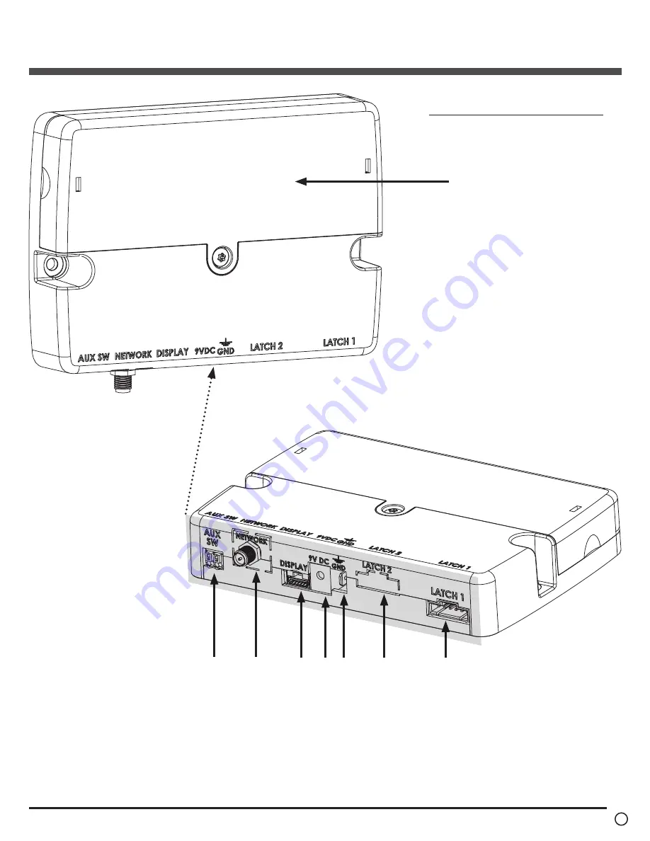
Cabinet eLock — Components

continued

Battery compartment

1

2

3

4 5

6

7

8

1. Door switch connector (door

switch not included)

2. Wi-Fi antenna cable connector

or Ethernet connector (Wi-Fi

connector shown; 300 Series only)

3. Battery cable connector

4. 2.5 mm AC adapter plug-in

(adapter not included)

5. Ground terminal
6. Dual eLatch connector (Latch 2, if

equipped; one latch is included)

7. Latch connector (Latch 1; one

latch is included)

8.  Battery pack cover (6-AA batteries

not included)

Screws to be used for mounting eLock 

battery compartment:

2 – #8 x 5/8” philips pan head wood 

screw for mounting battery compartment

Note

:

Battery compartment should be mounted 

within length of battery cable and latch 

cable.

Содержание CompX eLock 200 Series

Страница 1: ...ion instructions for networked and stand alone eLocks please see the Help section in CompX s LockView v4 software 1 Dot matrix LCD 2 Network button blue LED 3 UP button 4 NEXT SELECT button 5 BACK CAN...

Страница 2: ...lation example Cabinet door installation shown eLock can also be installed on drawers Battery cable connector Integrated Wi Fi antenna cable included for 300 Series Wi Fi version 200 300 Series Cabine...

Страница 3: ...r mounting Drill 7 32 through hole 1 for mounting 2 1 WARNING Print this page and measure the line above It is ONE INCH LONG If it measures less than or more than one inch the template measurements al...

Страница 4: ...200 300 Series CompX cabinet eLock Instructions 4 TEMPLATE ON OPPOSITE PAGE...

Страница 5: ...3 Battery cable connector 4 2 5 mm AC adapter plug in adapter not included 5 Ground terminal 6 Dual eLatch connector Latch 2 if equipped one latch is included 7 Latch connector Latch 1 one latch is i...

Страница 6: ...it for through hole battery cable w 3 8 drill bit for through hole Wi Fi antenna cable 300 Series Wi Fi only w 7 32 drill bit for through holes to mount eLock display unit w T15 pin in Torx 6 lobe bit...

Страница 7: ...PIN CREDENTIAL 1 Enter a valid PIN between 4 14 digits and 2 Press ENTER CARD CREDENTIAL If the eLock is equipped with a card reader HID Prox HID iCLASS or a Magstripe 1 Present a valid card within ra...

Страница 8: ...SETUP mode PASSAGE MODE LockView software required To hold the latch bolt in the open position indefinitely there is a setting in LockView called Passage Mode Passage Mode can be assigned to an eLock...

Страница 9: ...tton to highlight CREDENTIAL MENU and press NEXT SELECT 4 Highlight DELETE CREDENTIAL and press NEXT SELECT 5 Credential to Delete will be displayed All of the occupied slots along with the name if on...

Страница 10: ...ECT to edit highlighted credential 8 Press to change Level Supervisor User press UP DOWN to highlight 2nd PIN To add a new or change an existing 2nd PIN enter a 4 14 digit number using the numeric key...

Страница 11: ...ed 1 Press MENU LOGIN PLEASE will be displayed 2 Scan valid credential or enter 4 14 digit PIN and press ENTER 3 Press DOWN button to highlight LCD BACKLIGHT and press NEXT SELECT 4 LCD Backlight will...

Страница 12: ...eal time clock q Time based access restrictions q Create user groups q WindowsTM based q Set up Escalating Notification System q View Compliance Dashboard q Dual Latch access available second latch re...

Отзывы: