


Time Electronics
User Manual
7085A Temperature Distribution and 10 Channel Scanner Module
v1.1
7085A Temperature Distribution and 10 Channel Scanner Module
Page 11 of 21
2.6.2.1
Input
The input parameters apply to the dry calibrator and external reference probe is if used.
The input range is set to the minimum and maximum test points required.
Note:
When entering the input range, the values are duplicated to the output range to aid the user.
Calibration Instrument - Dry Block Calibrator Only
In this case the master reading is taken from the dry block’s internal reference. Select the
dry block from the
Input
calibrating instrument list.
Calibration Instrument - Dry Block Cali Reference Probe
In this case an external reference probe is used as the master reading. The 7051 DMM/
8060 AVM is used to measure the reading from the reference probe. Select the DMM + Dry
Block from the
Input
calibrating instrument list.
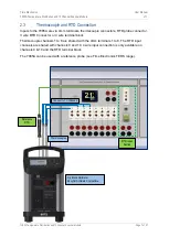
If the reference probe is a thermocouple the type and CJC reference options are made
available. Channel 1 is used for the thermocouple reference probe.
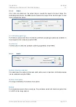
Wait For Stable
To achieve a high precision of measurement it is necessary to allow the dry block to stabilise.
EasyCal can be setup to wait until the temperature is stable before taking any further
measurements.
To use the dry block’s internal temperature stability feature (recommended) select ‘Use Jofra’.
This method takes between three and five minutes for stabilisation.
Alternatively EasyCal can monitor the readings and allow the tests to proceed after a number
of tests are with a set percentage of each other. The default settings for this type of stabilisation
are 10 readings within 1 percent of each other. These parameters can be modified in each
test if required.
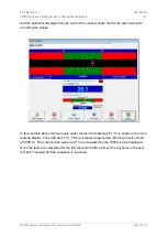
Setting Band
To ensure the test point is near the mean value required, a setting band for the input
temperature is set. A test will not proceed unless the value is within the setting band.


